Selected Portfolio

Industrial &
UX/Product Design

Diego A. López Ratti

02 / Profile & focus

Across object,
interface & use.

01Physical product design

02UX/UI & digital product work

03Healthcare / medical products

04CAD, product development & prototyping

05Biomedical engineering perspective

03 / Selected project index

Selected
work

  1. OXEEN Watch project overview

    01OXEEN Watch

    Resident monitoring wearableHealthcare · Connected Product · Industrial Design
  2. Custom Semi-Rigid Hand Prosthesis project overview

    02Custom Semi-Rigid Hand Prosthesis

    Personalized upper-limb prosthesisProsthetics · CAD · Additive manufacturing
  3. Infusion Pump Mounting Interface project overview

    03Infusion Pump Mounting Interface

    Structural reinforcement for a medical-device support component.Medical device · Engineering coordination · Prototyping
  4. Surgical Equipment Integration Drawers project overview

    04Surgical Equipment Integration Drawers

    Operating-room equipment integration systemHealthcare · System integration · Sheet metal · Project management
  5. Aerodam 360 project overview

    05Aerodam 360

    Dental turbine aerosol-control deviceDental · Clinical device · MJF · Project management
  6. Piip Camo project overview

    06Piip Camo

    Wireless low-latency live-streaming cameraConnected hardware · Industrial design · Electronics integration · Prototyping
  7. AER project overview

    07AER

    A physical–digital platform for customizable contemporary hand fans.Industrial design · Digital product · UX/UI · Generative AI · Production system
  8. [IMAGE PENDING]

    08UX/UI & Web Work

01 / Selected project

OXEEN Watch

Resident Monitoring Wearable
Healthcare · Connected Product · Industrial Design

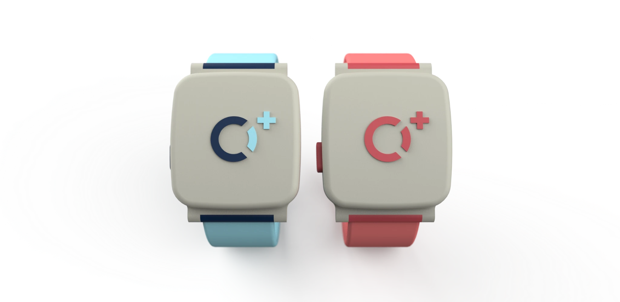
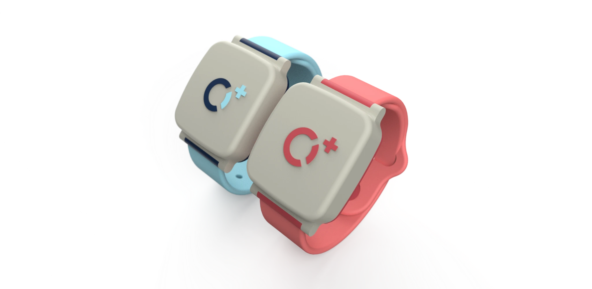
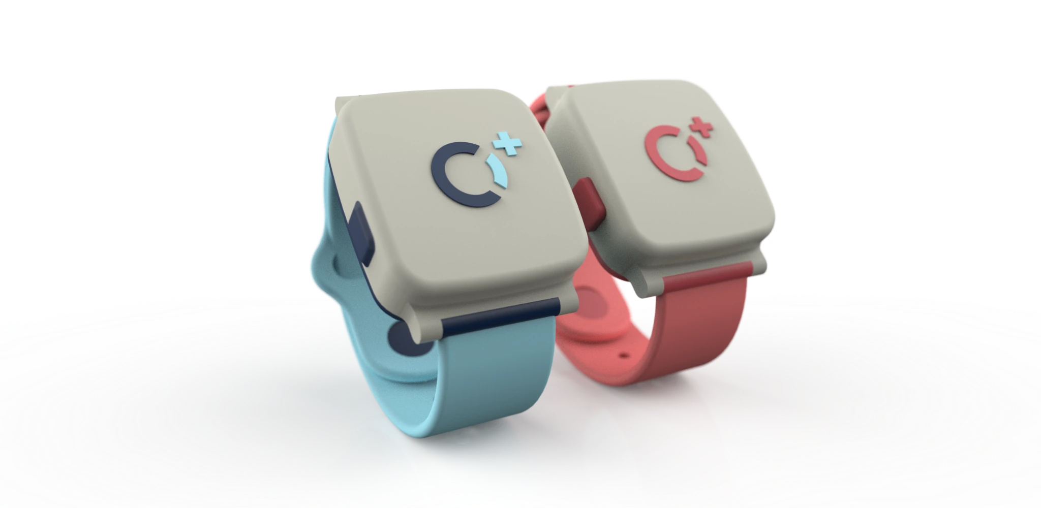
Blue and red OXEEN resident monitoring wristbands

Explore the redesign

Front views of the blue and red OXEEN Watch variants

Human-centred redesign

Designed for daily use in residential care.

This redesign focused on turning a test-phase device into a more usable, comfortable and visually approachable wearable.

Connected protection

Monitoring, safety and response in one device.

Blue OXEEN Watch shown from the front
  • Body temperature
  • Blood oxygen
  • BPM
  • Fall detection
  • SOS button
  • Resident location

A connected wearable designed to support faster, more informed care.

Engineering / enclosure design

Designed around the electronics.

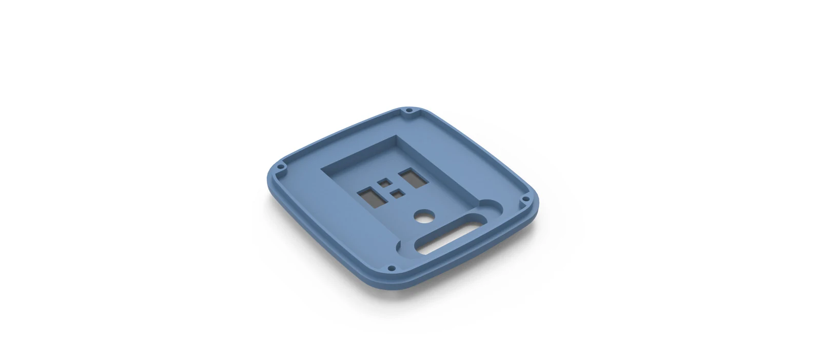
The redesign required translating electronic constraints into a compact, prototype-ready wearable enclosure.
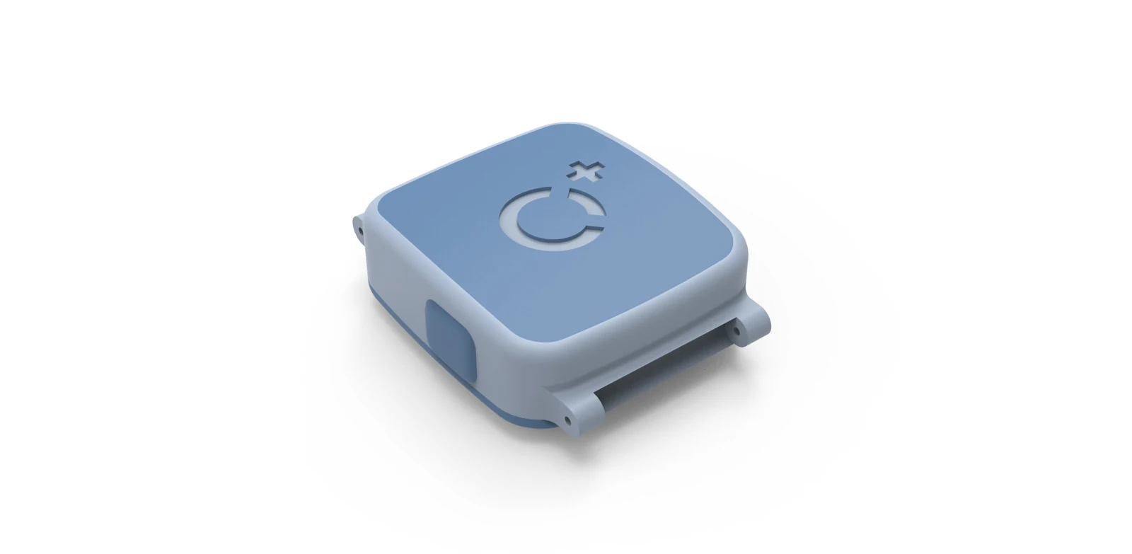
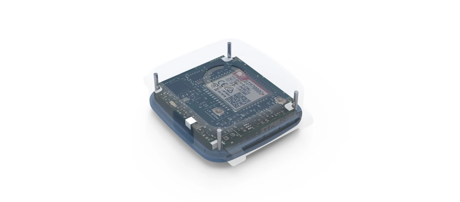
OXEEN outer enclosure CADExisting electronics positioned within the OXEEN enclosure architectureInternal shell architecture of the OXEEN wristband
  • PCB integration
  • Internal architecture
  • Strap attachment
  • Prototype-ready CAD

Product context

Part of a connected care ecosystem.

The wearable sends resident data into a centralized monitoring system, connected through LoRaWAN infrastructure and surfaced through platform and app interfaces.

  1. 01Blue OXEEN WatchOXEEN Watch
  2. 02LoRaWAN
  3. 03Gateway
  4. 04Cloud
  5. 05Platform / App

Connected ecosystem shown as product context.

Role

My contribution

Lead product designer for the wristband redesign.

  1. Concept development
  2. CAD
  3. Enclosure design
  4. Prototyping
  5. Rendering
  6. Project management
Top view of blue and red OXEEN Watch variants

OXEEN × INNOU

Physical product,
connected care.

A healthcare wearable redesign balancing usability, electronic integration and system connectivity.
02 / Selected project

Custom
Semi-Rigid
Hand Prosthesis

Personalized upper-limb prosthesis for congenital partial hand absence.

Prosthetics · User-centred design · CAD · Additive manufacturing

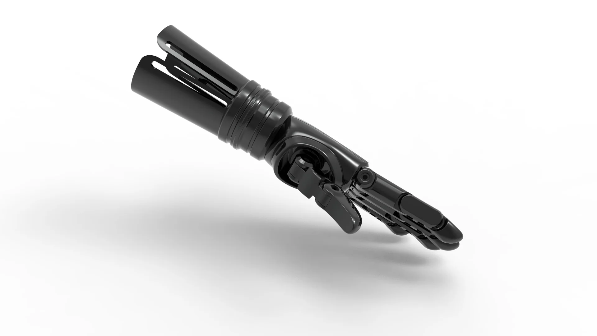
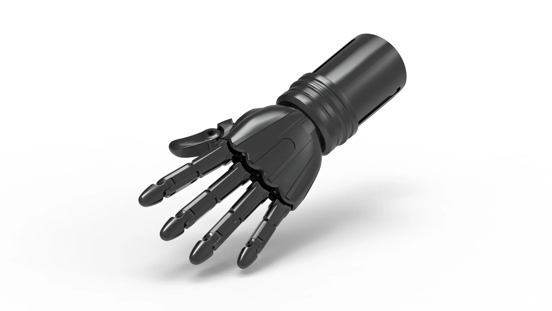
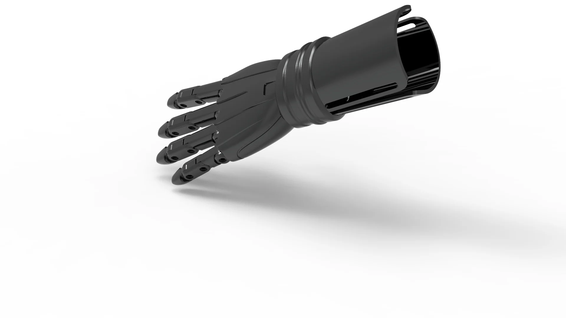
CAD render of the custom semi-rigid hand prosthesis
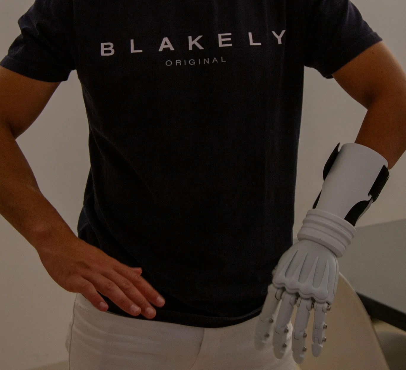
Custom prosthesis worn by the user during a fitting session

User-specific design

Designed around one person,
not a standard size.

The project began with a user with congenital absence of the hand and partial wrist anatomy, looking for an affordable prosthesis primarily for everyday and social use.

The goal was a comfortable, personalized device that could also be worn under a glove to approximate the appearance of a natural hand.

Visual direction requested by the user: Deus Ex–inspired.

Functional development

Turning an aesthetic model
into a wearable prosthesis.

The initial geometry required functional development in SolidWorks to accommodate articulation, assembly, the residual-limb interface and additive manufacturing.

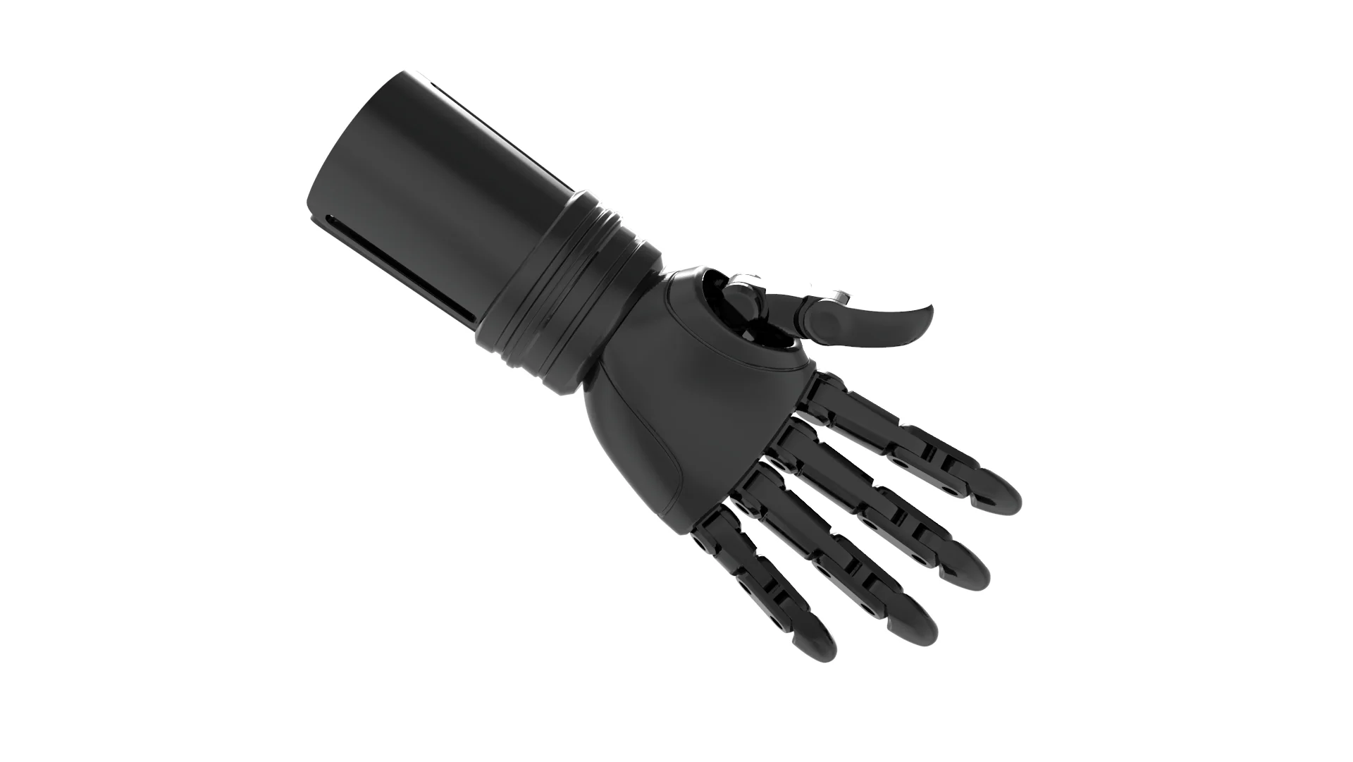
Dorsal CAD view of the prosthesisUnderside CAD view showing articulated finger hardwarePalm-side CAD view of the prosthesis

Aesthetic geometry articulation wearable architecture

Articulation

Positionable by hand.
Stable in use.

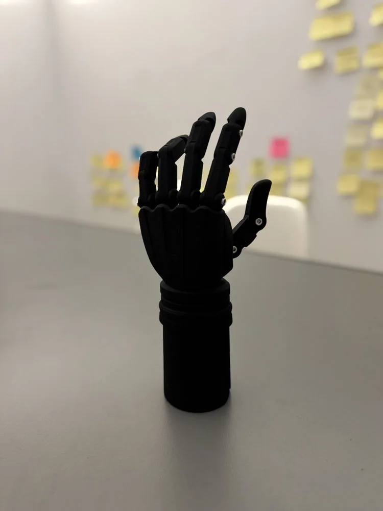
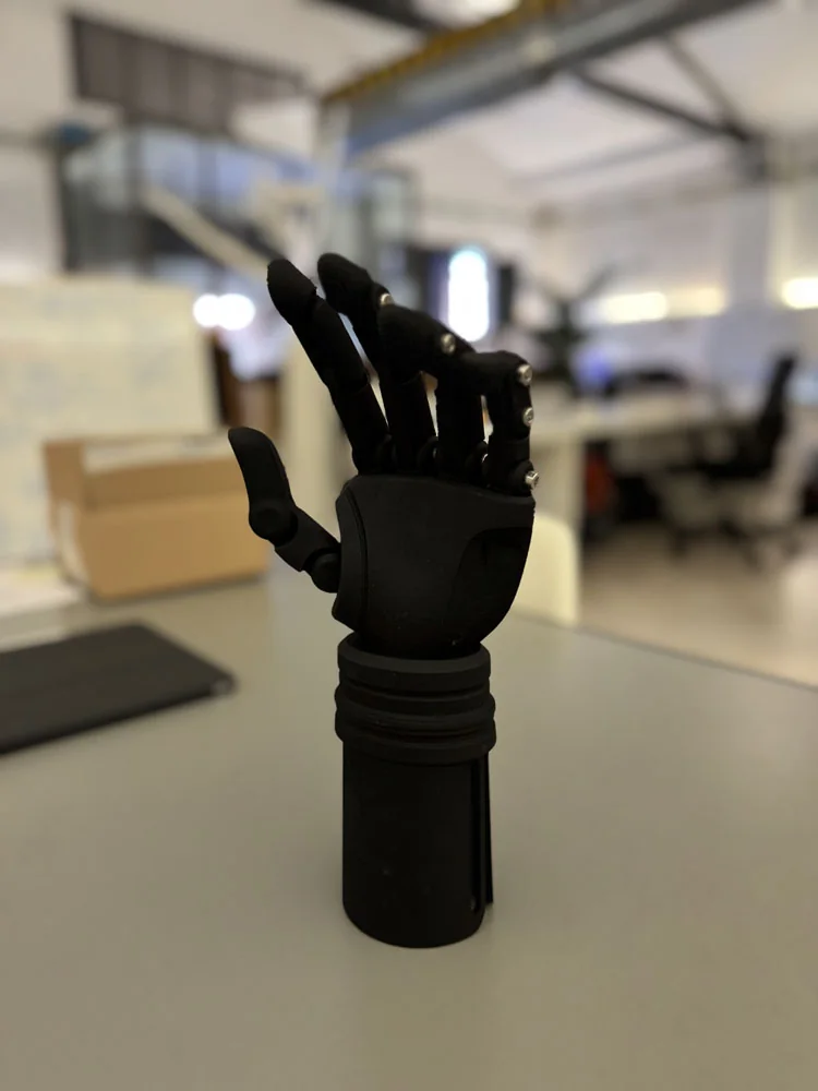
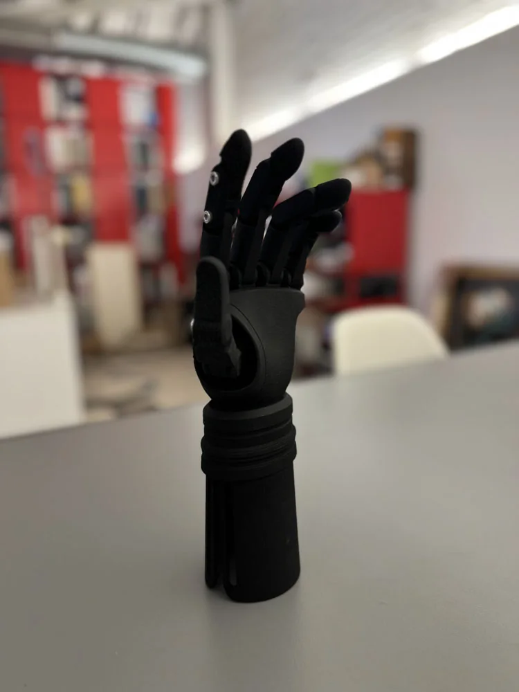
Each finger can be manually repositioned using the opposite hand and remains rigid in the selected pose.

The solution prioritised visual versatility and everyday simplicity rather than powered actuation.

Physical prosthesis with its manually positionable digits posed
  • Manually positionable digits
  • Articulated thumb
  • Standard mechanical hardware
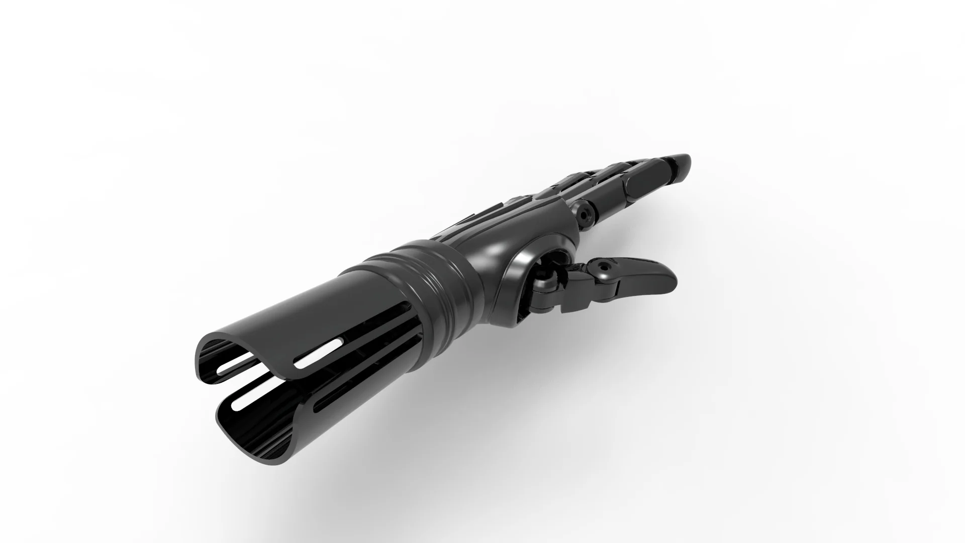
Detailed CAD view of the slotted residual-limb interface

Custom interface

Designed for the user's
remaining anatomy.

The prosthesis interfaces with the residual limb through a prosthetic cotton sleeve and a Velcro compression strap, allowing the device to be secured around the remaining wrist anatomy.

Residual-limb interface

Additive manufacturing

From CAD
to a fitted physical prosthesis.

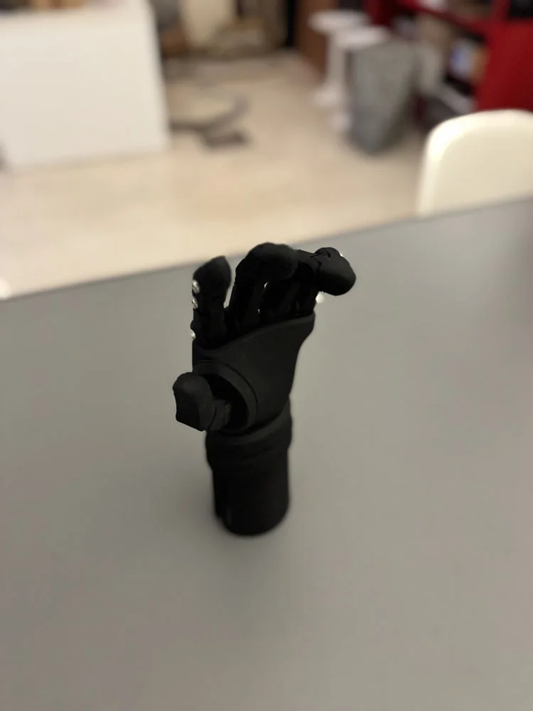
The final device was produced as a single MJF-manufactured unit and assembled using standard screws and mechanical hardware.

Front view of the black MJF-manufactured prosthesisThree-quarter view of the physical prosthesisSide view of the physical prosthesisPhysical prosthesis with manually positioned fingers

One final physical unit · MJF · Mechanical assembly

User fitting

Designed,
fitted and evaluated
with the user.

The final prosthesis was fitted directly with the user to assess positioning, comfort and everyday usability.
The user reported being satisfied with the final result and comfortable wearing the device.

Prosthesis worn during the user fittingUser manually repositioning the prosthesis fingers with the opposite hand

Manual repositioning demonstrated during the fitting session.

My contribution

From brief
to physical fitting.

Lead designer for the functional adaptation, CAD development, prototyping and fitting phases.

  1. Brief analysis
  2. Functional concept adaptation
  3. SolidWorks CAD
  4. Mechanical development
  5. Prototyping
  6. Fitting
  7. Project management

Custom prosthetics

Designed around anatomy,
identity and use.

A custom prosthetic solution balancing appearance, comfort, manufacturability and cost.

Palm view of the finished custom hand prosthesis

03 / Selected project

Infusion Pump
Mounting Interface

Structural reinforcement for a medical-device support component.

Medical device · Engineering coordination · Functional prototyping

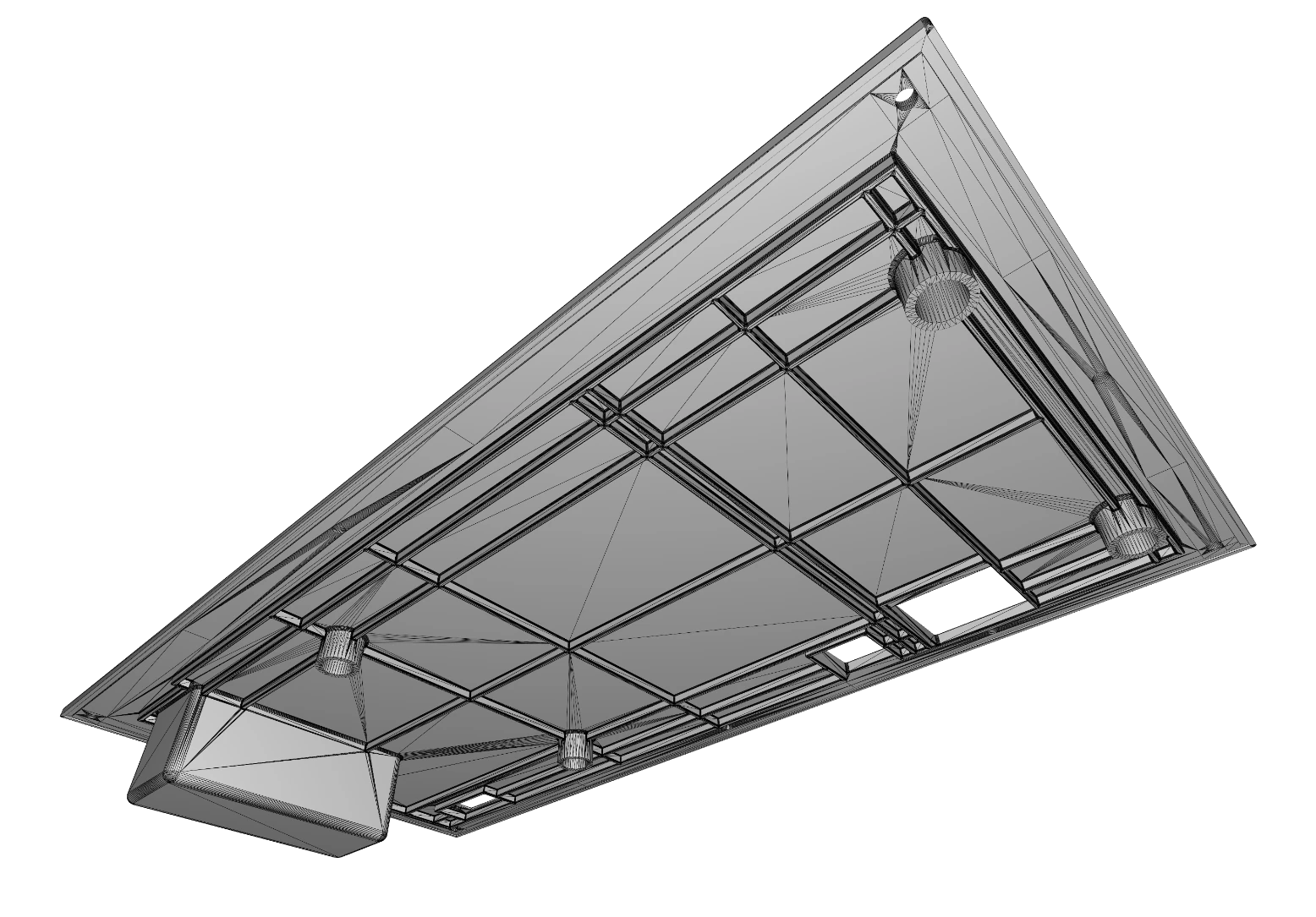
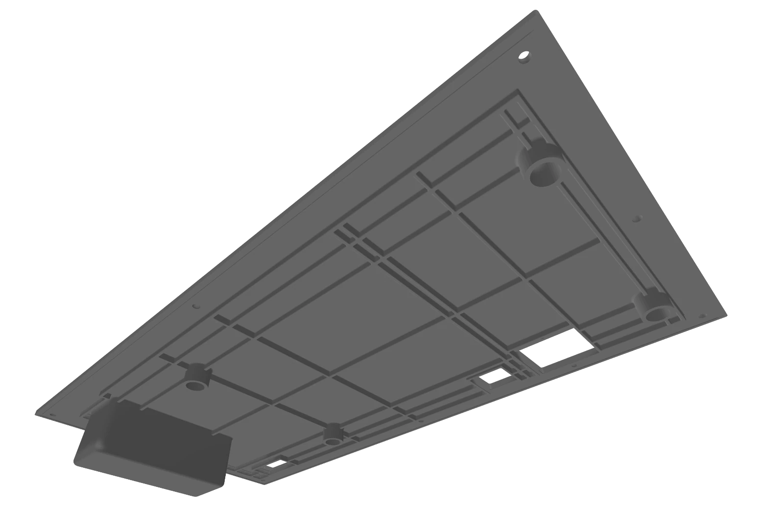
Underside of the mounting interface showing its reinforced rib architecture

Targeted engineering

Reinforcing the
critical interface.

Rather than redesigning the full device, the project focused on a specific structural component connecting the infusion-pump assembly to a mobile hospital pole system.

The objective was to strengthen the existing architecture while preserving the component's dimensional and assembly constraints.

Wireframe view of the interface underside geometryShaded view of the interface underside structure
Geometry / structureRib architectureMounting pointsAssembly constraints

Project management / engineering

From client requirements
to prototype-ready geometry.

My role was to translate client requirements into actionable technical briefs, coordinate the engineering development and manage communication throughout the iteration process.

The work combined project management with enough technical understanding to evaluate constraints, communicate priorities and keep the prototype-development process aligned with the original brief.

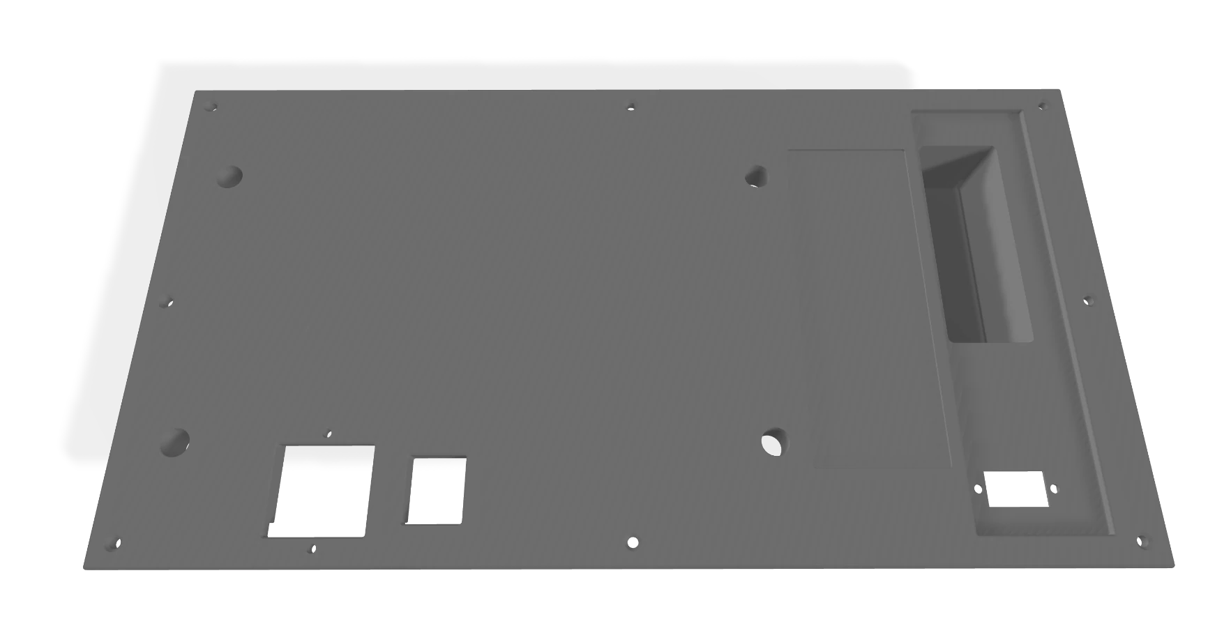
Original engineering drawing documenting the interface plate dimensions and details
Engineering documentation

Functional prototyping

A focused mechanical
revision.

The revised component was prepared for functional prototyping through additive manufacturing, allowing the updated geometry and assembly strategy to be evaluated physically.

Medical-device hardware

Engineering coordination
for real medical hardware.

A compact project centred on structural reinforcement, client-facing technical coordination and functional prototype development within an existing medical-device architecture.

Role

  • Project Management
  • Client Communication
  • Technical Briefing
  • Prototype Coordination
Large top view of the mounting interface geometry

04 / Selected project

Surgical Equipment
Integration Drawers

Operating-room equipment integration system

Healthcare · System integration · Sheet metal · Project management

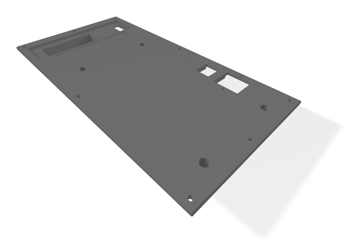
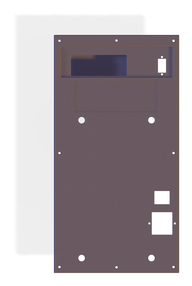
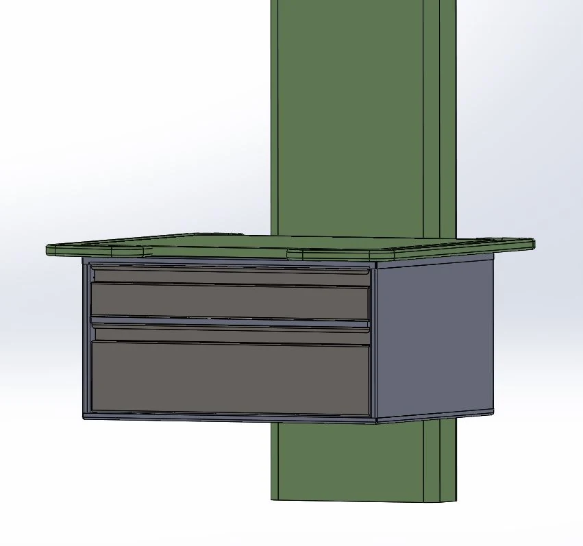
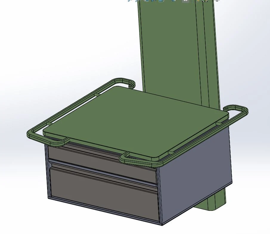
Technical CAD overview of the two-drawer equipment integration enclosure

A rapid engineering project focused on packaging, integration and low-volume production of a custom drawer system for operating-room equipment.

System integration

Designed around
the equipment.

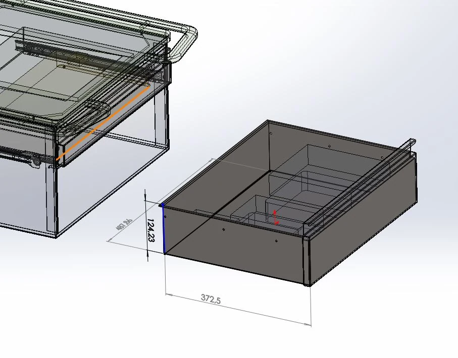
The project started from a defined installation envelope and the dimensions of the hardware that had to be integrated inside it. The challenge was to translate those constraints into a compact two-drawer architecture that remained accessible, manufacturable and suitable for installation within an operating-room workstation.

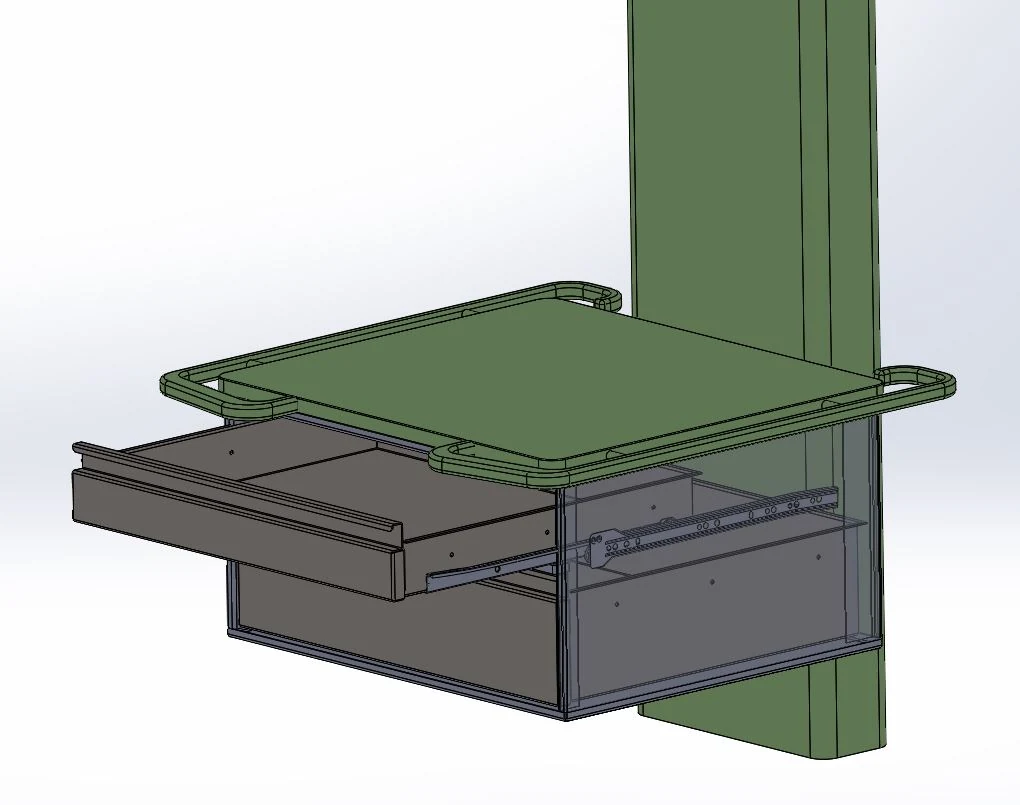
CAD view of the equipment enclosure with its lower drawer open
Constraint-driven system architecture

Packaging

Two drawers.
Different requirements.

The internal architecture was developed around the actual equipment rather than generic storage volumes. Each drawer responded to different component dimensions, clearances and access requirements.

Technical layout of the equipment-specific upper drawer
Upper drawerEquipment-specific integration
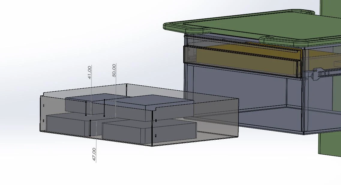
Technical layout of larger hardware within the lower drawer
Lower drawerLarger-volume hardware packaging

Engineering development

Every millimetre
had a purpose.

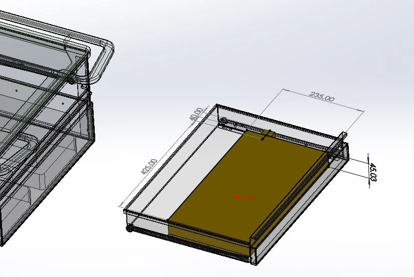
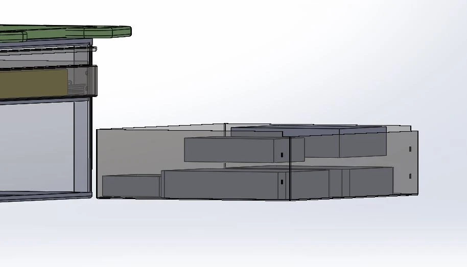
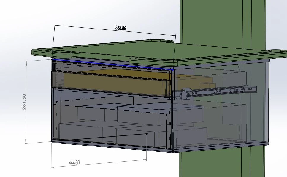
Component volumes, drawer travel, structural boundaries and installation clearances were coordinated within a tightly constrained envelope. CAD became primarily a tool for packaging and technical decision-making.

Detailed CAD packaging study of hardware in the lower drawerSide-view CAD study of component clearances in the lower drawerTransparent dimensional engineering view of the complete drawer enclosure
  • Equipment volume
  • Drawer travel
  • Access clearance
  • Structural envelope

Low-volume production

Engineered to
be built.

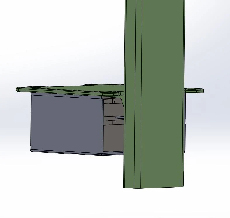
The final enclosure was developed for low-volume fabrication using folded sheet metal, CNC-cut features and additional machining operations. The objective was a robust, straightforward assembly that could move quickly from engineering definition into production.

Closed front view of the fabricated drawer enclosure designRear CAD view showing the enclosure relationship to the workstation column
  1. 01CAD definition
  2. 02Sheet-metal fabrication
  3. 03Assembly
  4. 04Installation

Real equipment

Designed around
real hardware.

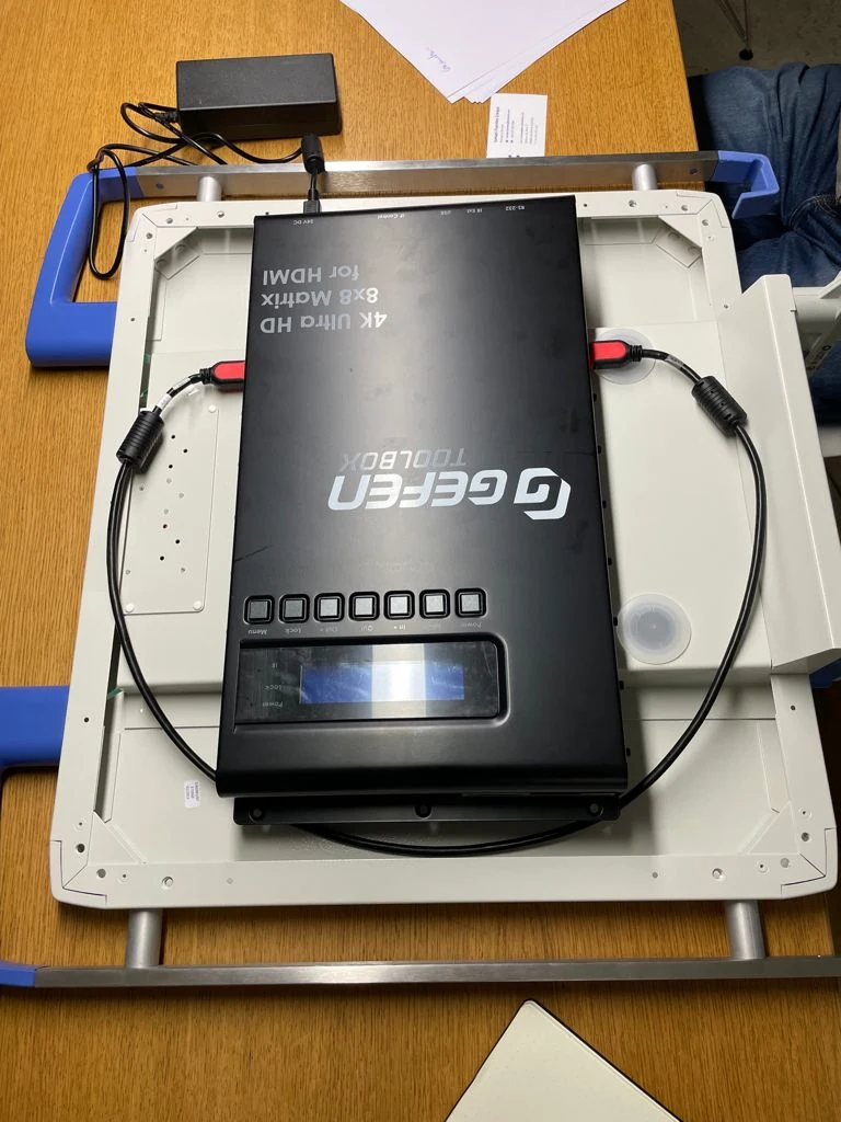
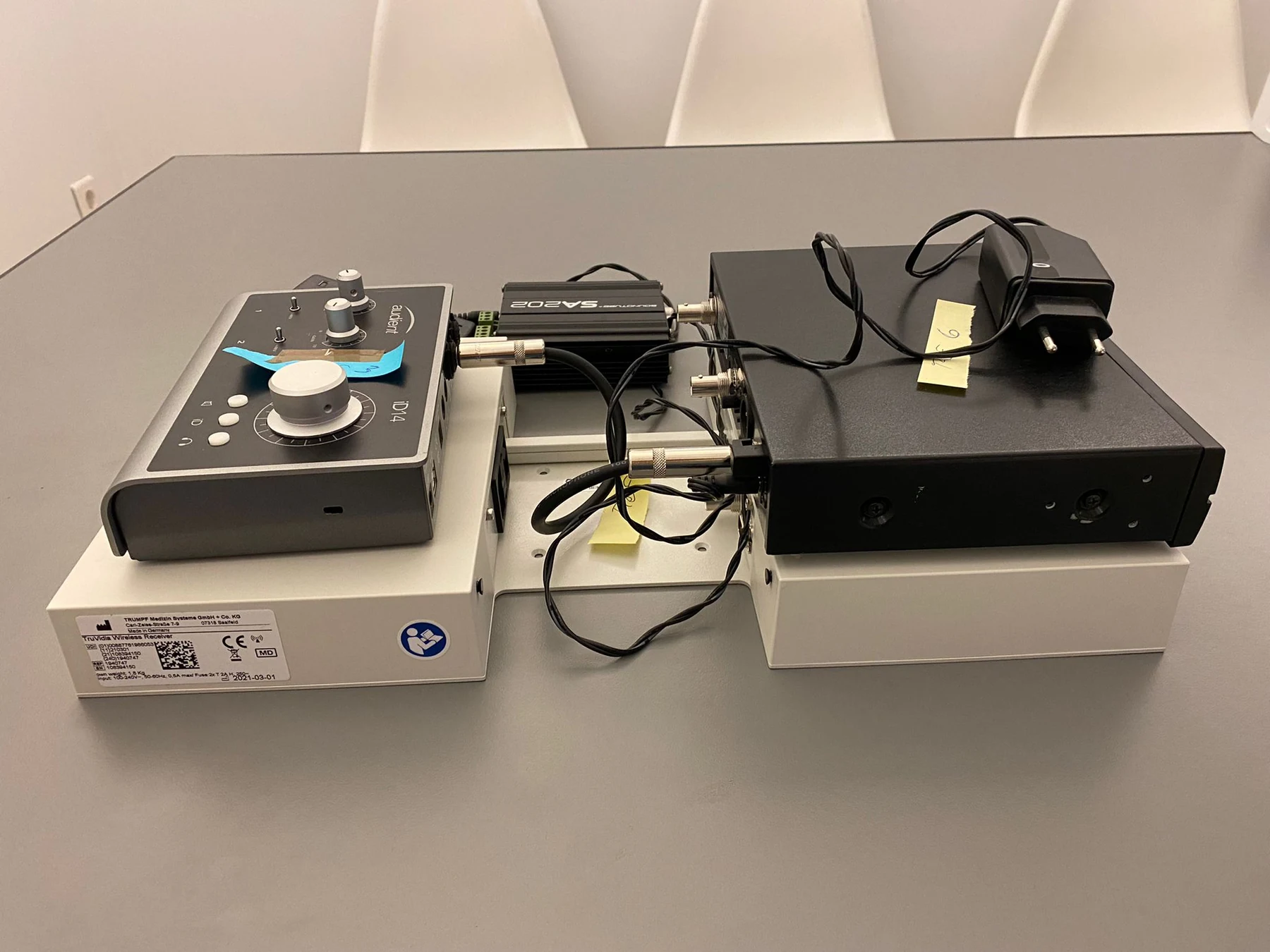
Packaging decisions were based on the actual devices that had to be accommodated. Physical equipment was used to validate scale, cable routing, accessibility and the final integration strategy.

Physical equipment positioned inside the real drawer and workstation
Installation fit
Hardware arranged for bench validation during system integration
Bench validation

My role

Coordination between
client, engineering
and production.

My contribution centred on project management and technical coordination: receiving requirements from the client, translating them into an engineering brief, coordinating development and supporting the project through prototype and production decisions.

  1. Project Management
  2. Client Communication
  3. Technical Coordination
  4. Engineering Briefing
  5. Production Coordination

Production outcome

Two units.
Built and installed.

A compact, fast-moving engineering project that turned equipment, dimensional and manufacturing constraints into two completed operating-room integration units.

Fast engineering · Real hardware · Installed outcome
Completed two-drawer equipment integration system shown open

05 / Selected project

Aerodam
360

Dental Turbine Aerosol-Control Device

Dental · Clinical device · MJF · Project management

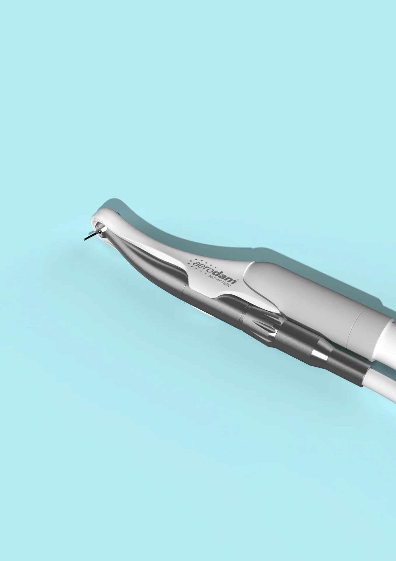
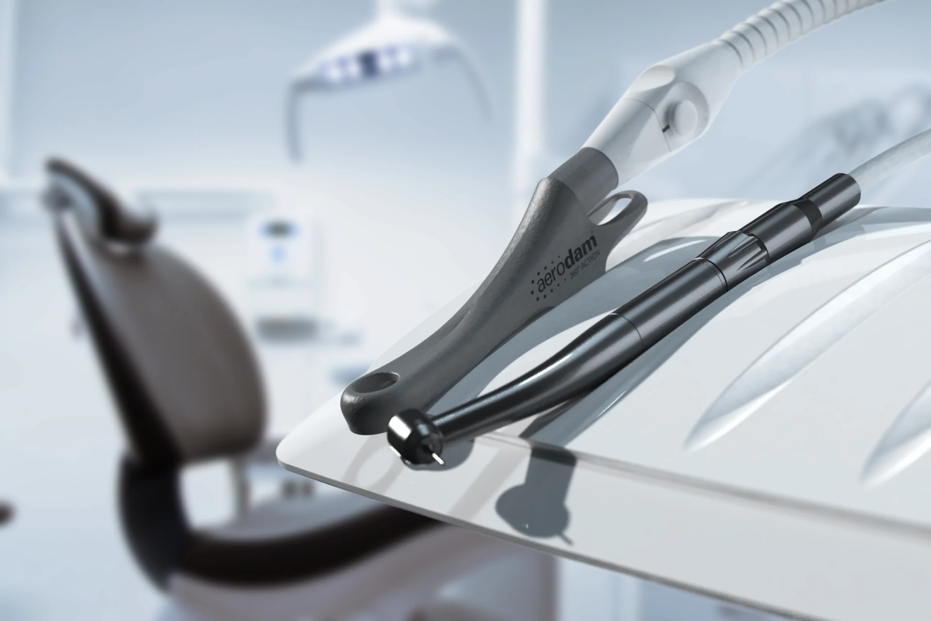
Aerodam 360 suction accessory in a dental treatment context

A compact suction accessory developed around the dental turbine to capture aerosol at source while preserving clinical access and one-hand handling.

Aerosol control

Capture aerosol
at the source.

Aerodam integrates suction directly around the turbine head, bringing the aspiration point closer to where aerosol is generated while keeping the assembly compact enough for clinical use.

Blue technical render illustrating suction around the Aerodam turbine head
  • Turbine head
  • 360° suction zone
  • Aspiration connection
  • Compact envelope

Clinical integration

Built around
existing hardware.

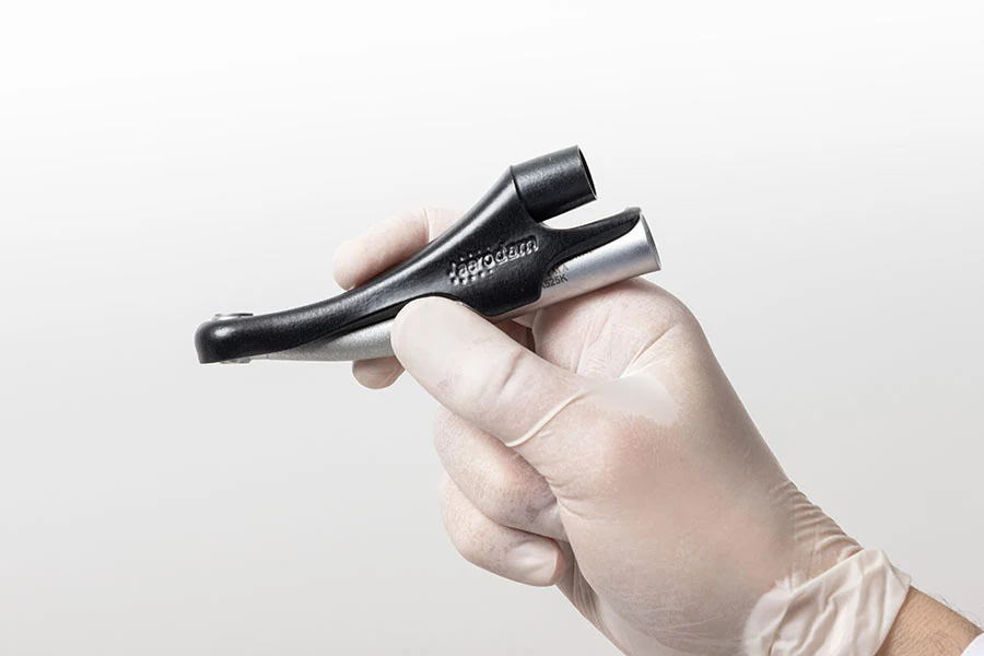
The product had to integrate with an existing dental turbine rather than define a new instrument from scratch. Geometry, attachment, suction routing and overall volume therefore had to coexist within a very limited clinical envelope.

Aerodam accessory held in a hand to demonstrate its compact scale
Scale in hand
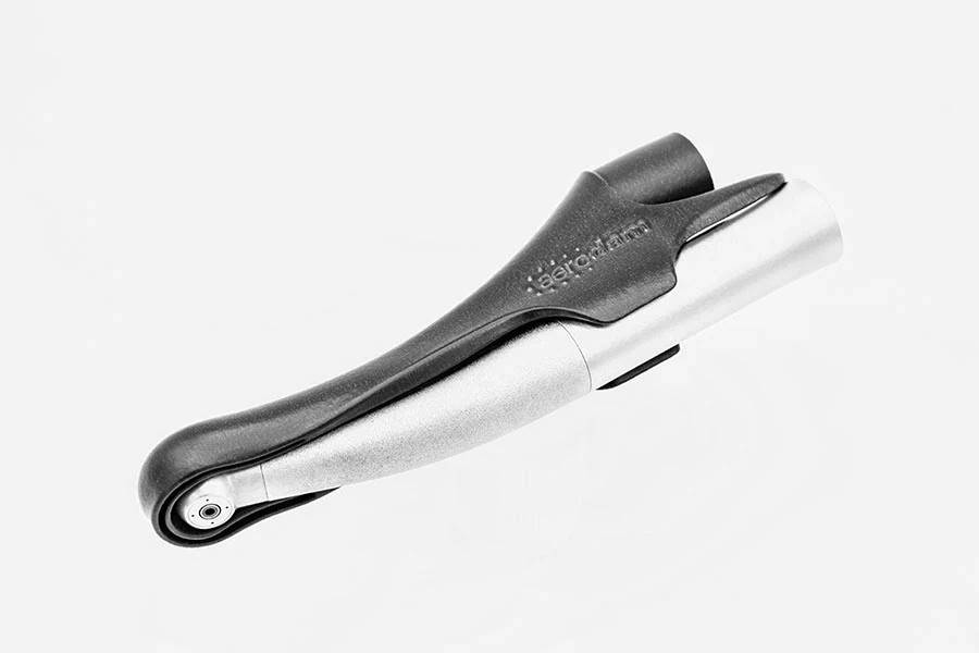
Aerodam mounted on an existing dental turbine
Mounted assembly
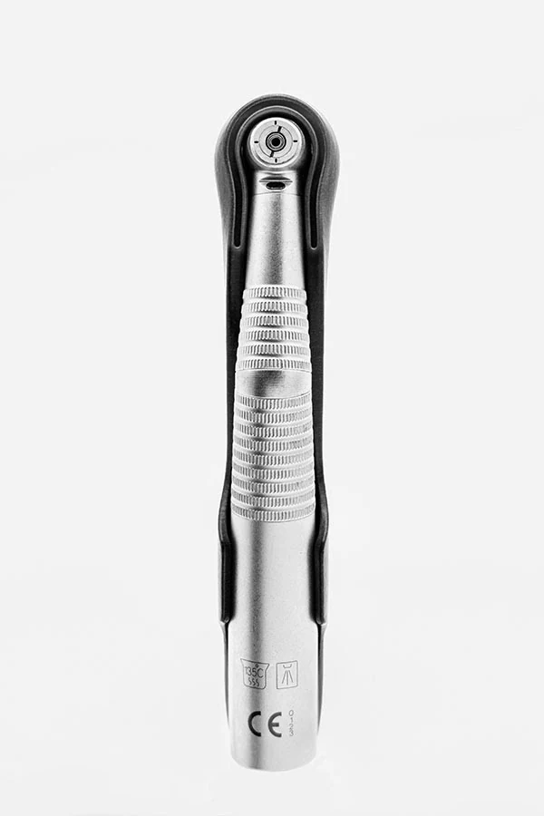
Front view of the Aerodam interface surrounding the turbine head
Head interface

Form development

Geometry shaped
around the turbine.

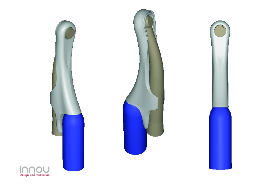
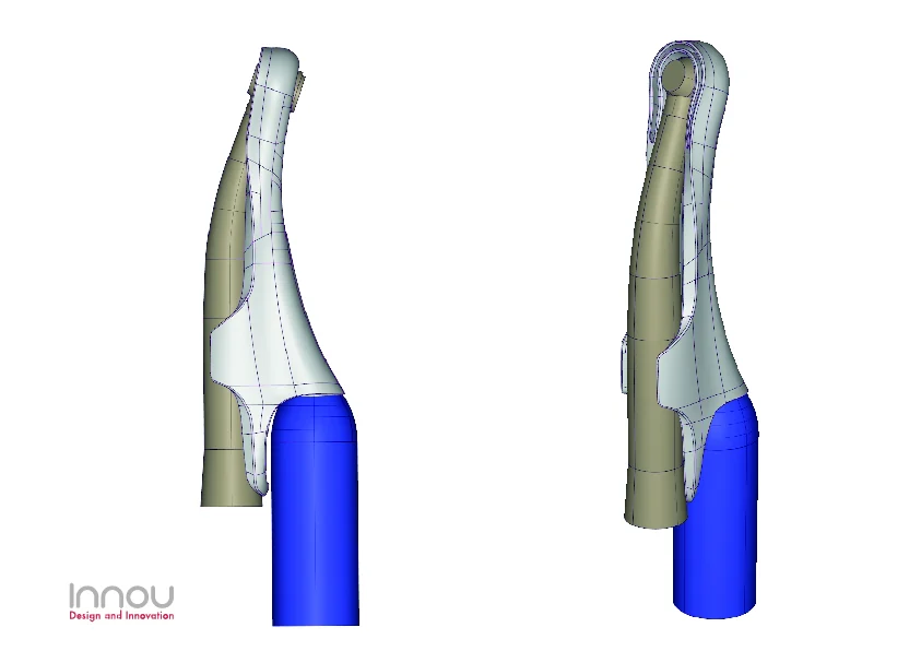
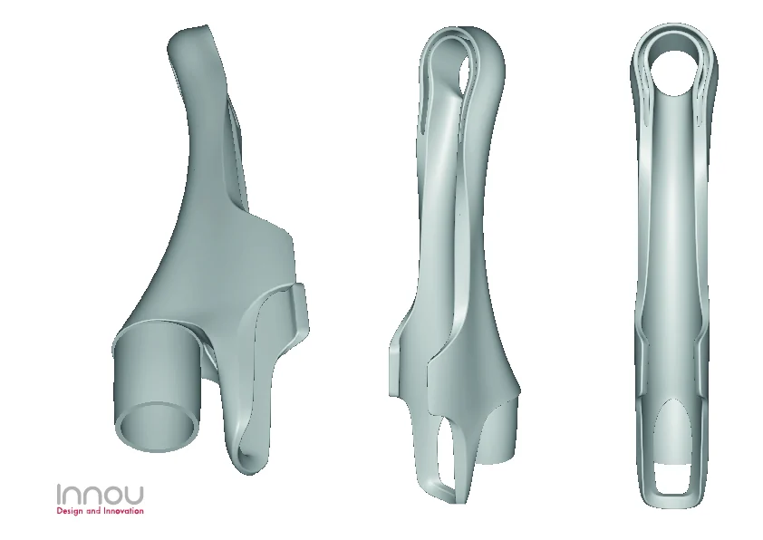
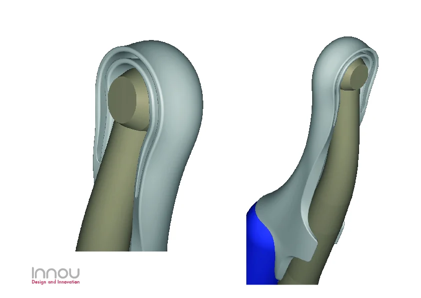
The development process progressively resolved the relationship between the turbine body, the head interface, the aspiration connection and the external housing.

Early CAD concept views of Aerodam around the dental turbineCAD surface development of the Aerodam housingDeveloped CAD body views of AerodamDetailed CAD view of the Aerodam turbine-head interface

Production

MJF, finished
for clinical production.

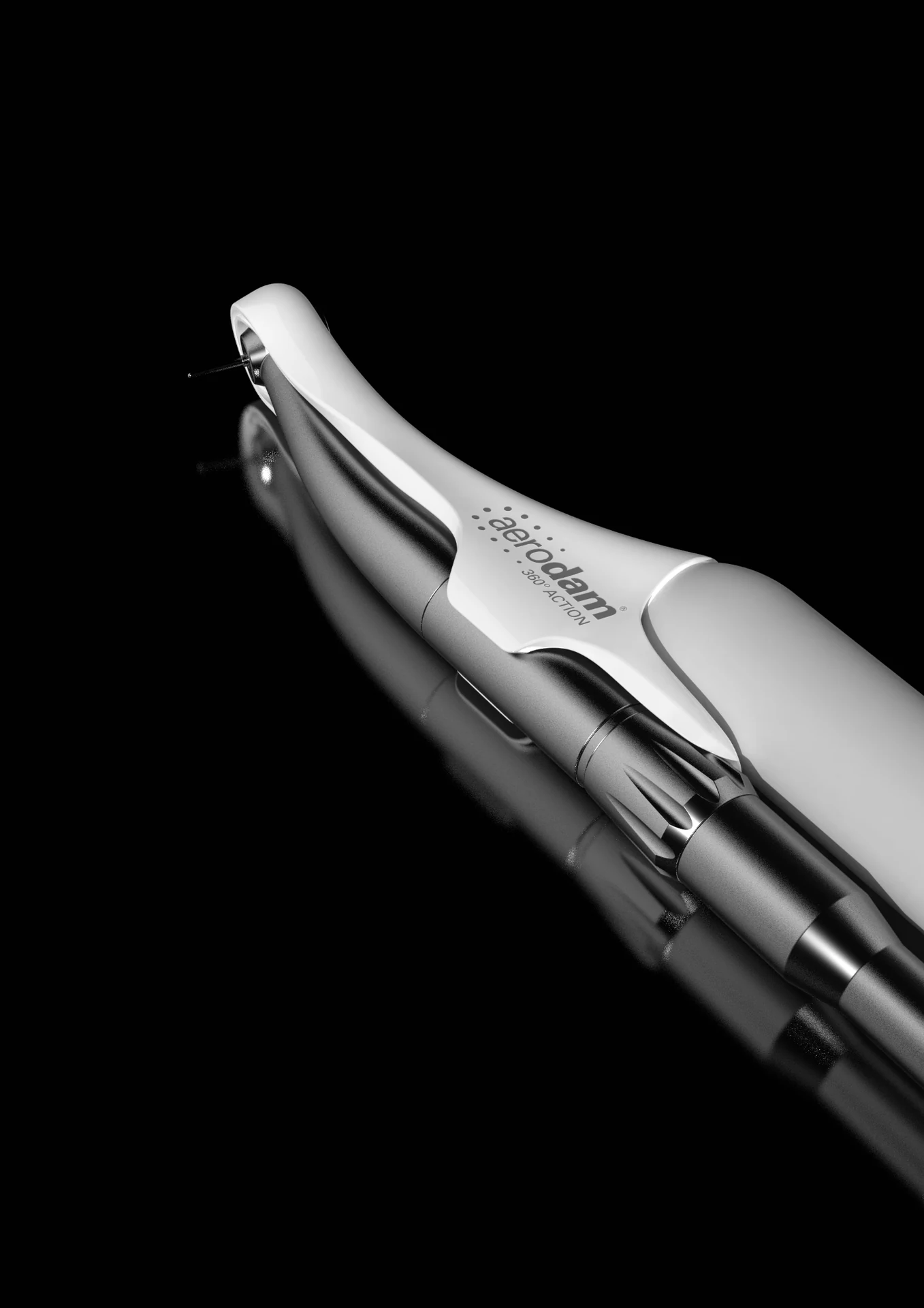
The final part moved into Multi Jet Fusion production and Vapor Smoothing. This combination provided the geometry, surface quality and finishing route required for the finished product and its certification process.

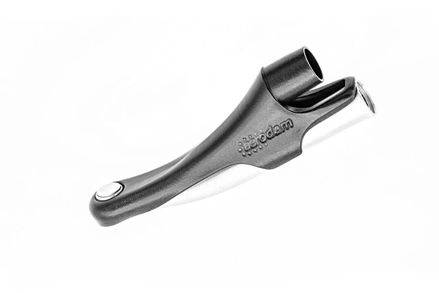
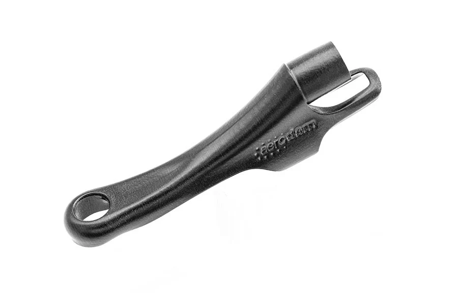
Finished Aerodam product in a three-quarter viewFinished Aerodam housing shown separately
  • MJF
  • Vapor Smoothing
  • Final Production
  • Certification Process
Aerodam product render against a black background

Project management + communication

Coordinating the product.
Communicating the product.

My role centred on project management: coordinating communication with the client, quotation, prototypes and production. In parallel, I personally developed the project's visual communication through renders, animations and the recording and editing of explanatory and promotional video content.

  1. Project Management
  2. Client Communication
  3. Quotation Coordination
  4. Prototype Coordination
  5. Production Coordination
  6. Renders
  7. Animation
  8. Video Production

Aerodam 360

From development
to a real clinical product.

A compact dental-device project connecting client coordination, prototyping, advanced additive manufacturing and visual communication through to final production.

Aerodam 360 mounted on the finished dental turbine

06 / Selected project

Piip
Camo

Wireless Low-Latency Live-Streaming Camera

Connected Hardware · Industrial Design · Electronics Integration · Prototyping

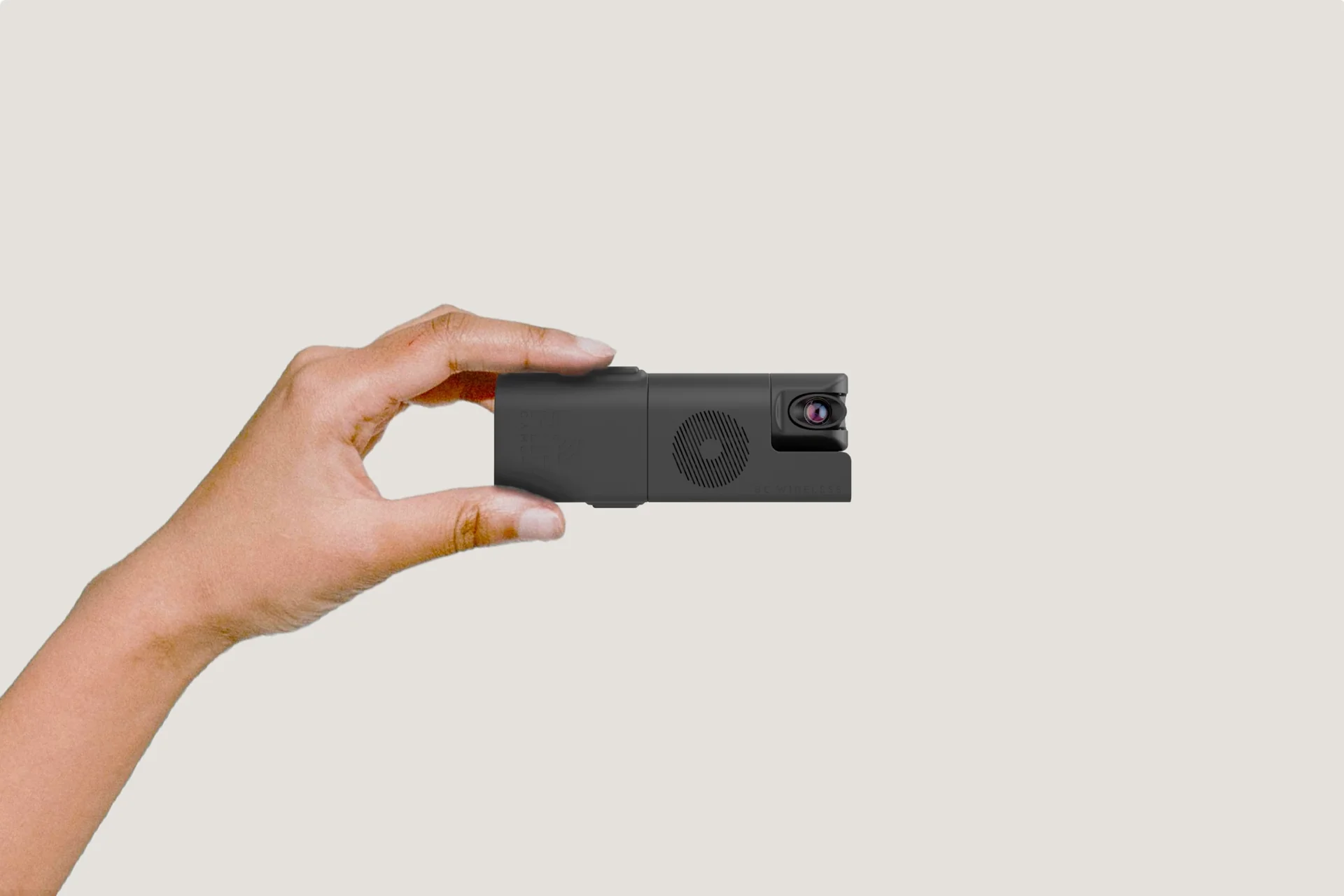
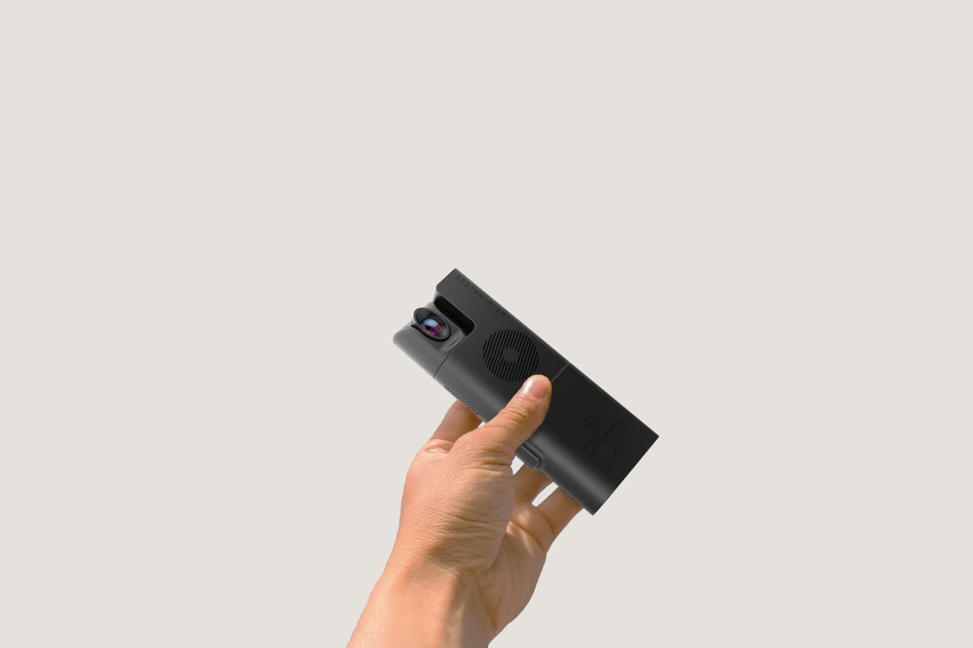
Piip Camo wireless camera held in a hand

A compact wireless camera redesigned around the practical constraints of professional on-set monitoring.

On-set hardware

A compact camera
built around real
production constraints.

The redesign focused on usability, camera positioning, thermal management and rapid battery replacement while integrating the existing electronics into a compact portable architecture.

Piip Camo shown at handheld scale

Camera orientation

Reposition the view.
Not the whole device.

The camera module was integrated into a rotating turret, allowing extensive directional adjustment while keeping the main body in position.

This was a major usability requirement for an on-set monitoring device that may need to be placed or mounted in changing environments.

Piip Camo camera module with rotating turret

Electronics integration

Designed around
the hardware inside.

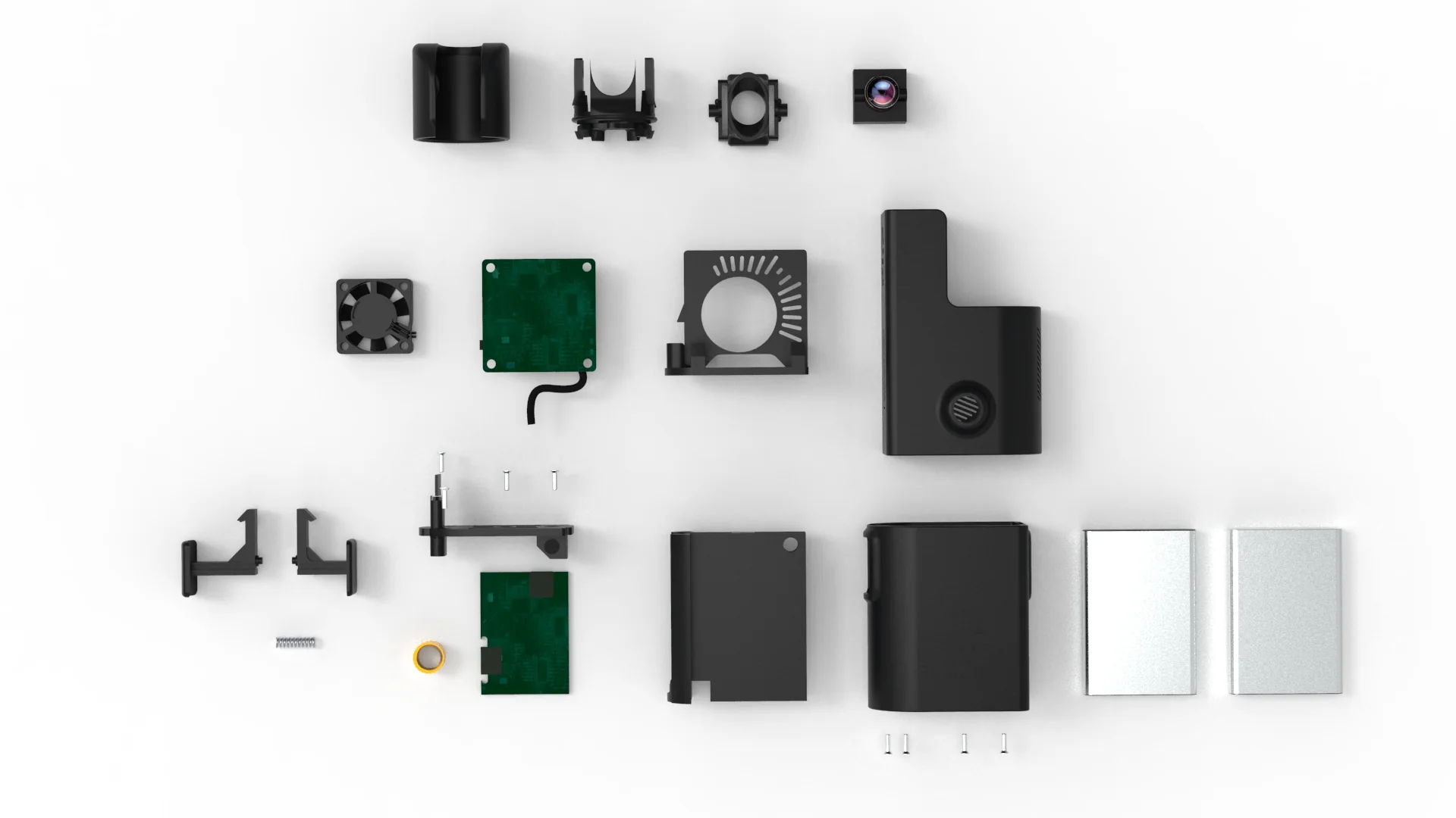
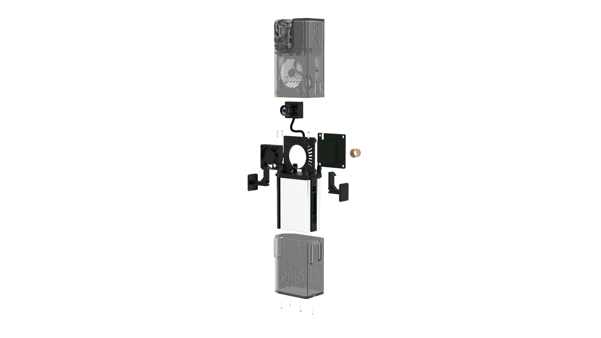
The enclosure architecture was developed around the existing camera, electronics, cooling components and power system rather than treating them as an afterthought.

Exploded Piip Camo system showing its enclosure and internal hardware architecture
Top exploded view of the Piip Camo components
Camera · Electronics · Cooling · Battery · Enclosure

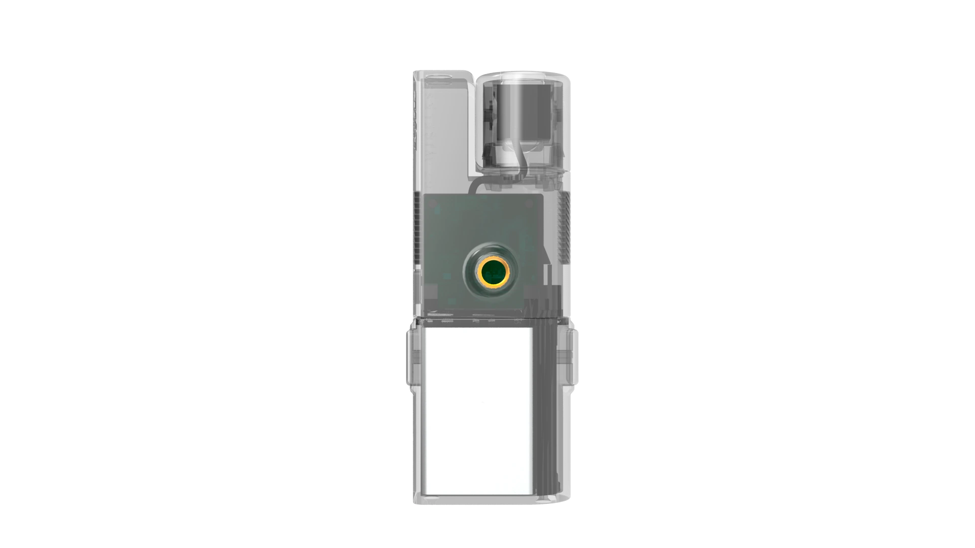
Thermal management

Compact hardware
still needs to breathe.

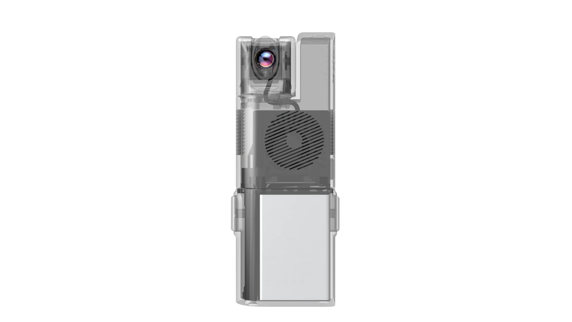
Heat dissipation was a central constraint of the redesign. Internal packaging, ventilation geometry and cooling components were considered together with the external enclosure.

Transparent front view of Piip Camo internal architectureTransparent rear view of Piip Camo internal architecture

Modular power

Battery changes
without interrupting
the hardware architecture.

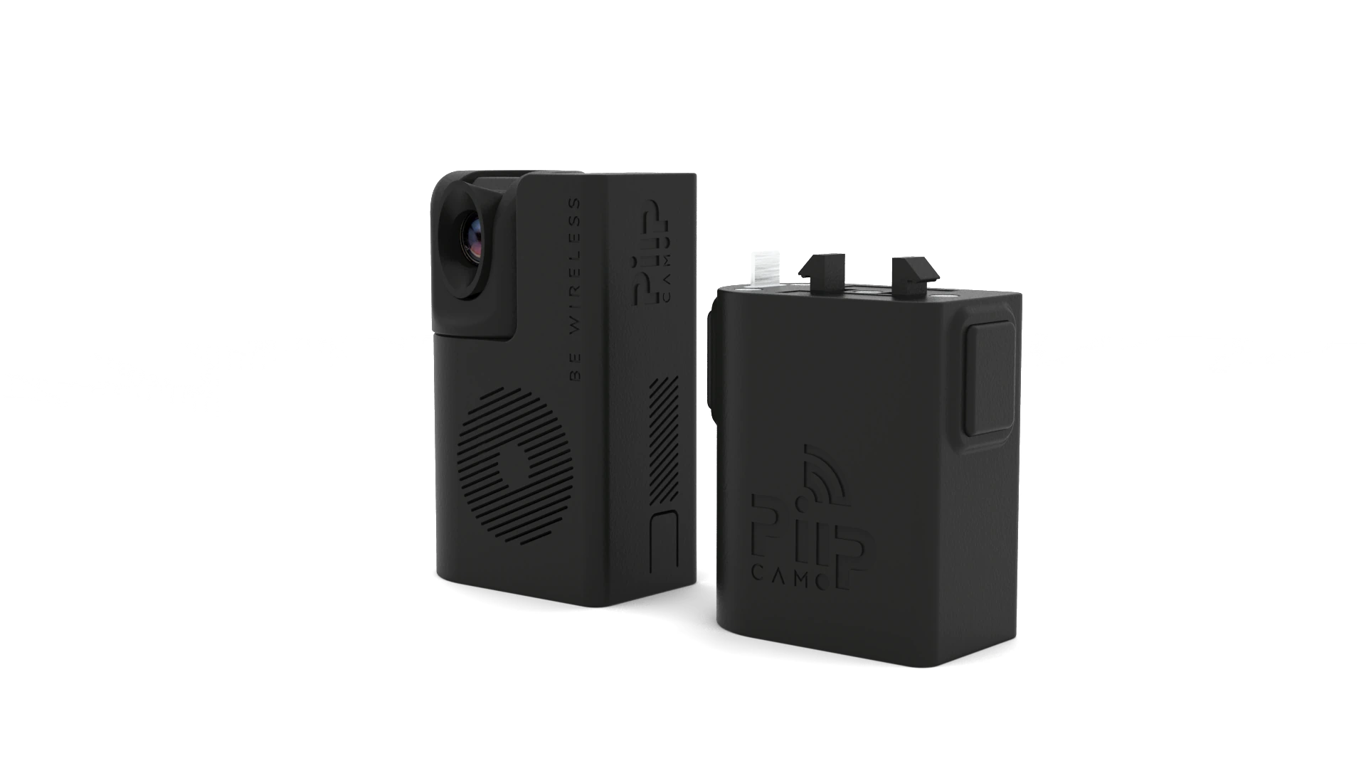
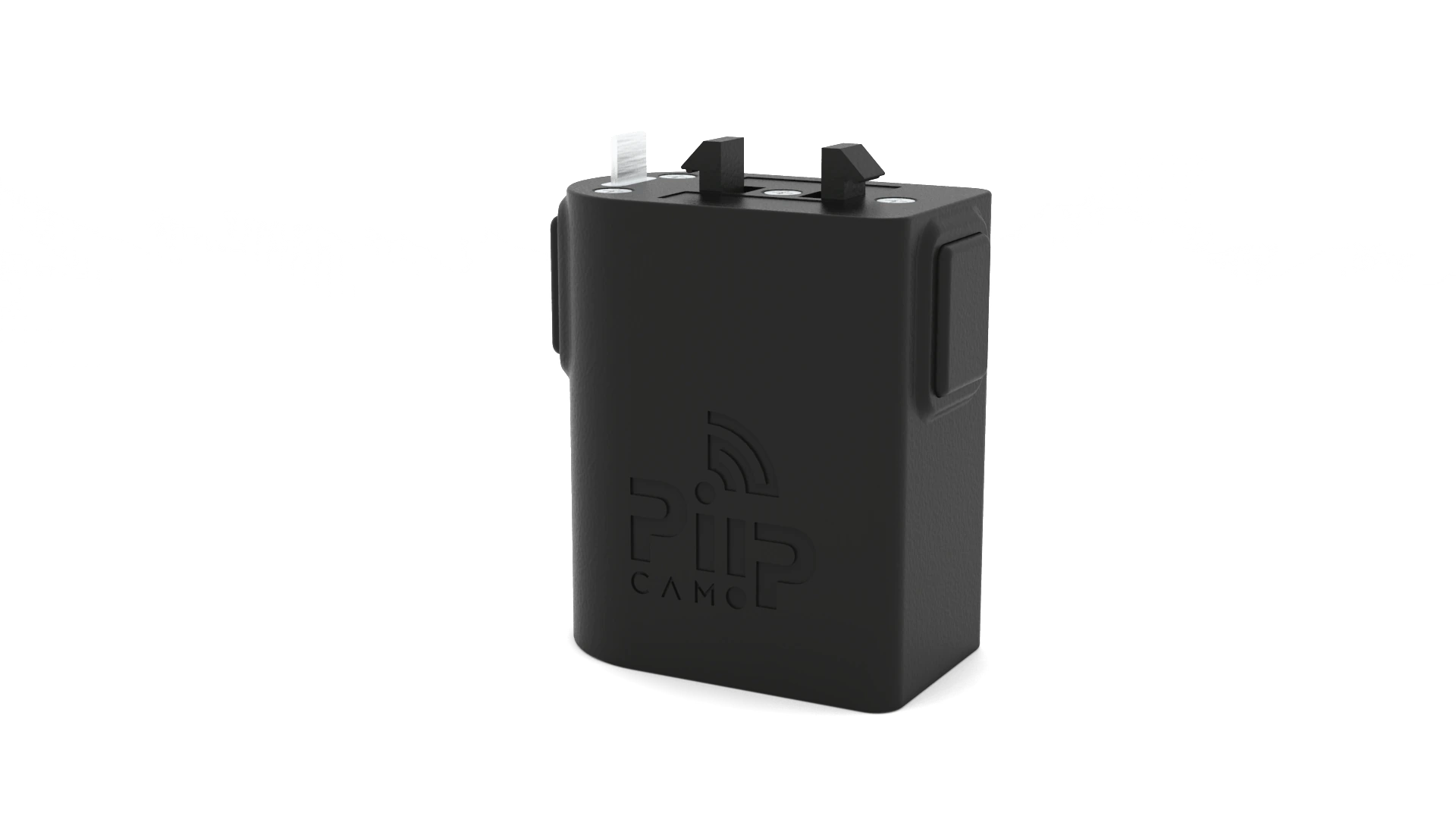
The lower power module was designed as a removable part of the product architecture, with its attachment geometry developed for straightforward battery replacement and robust everyday handling.

Piip Camo upper camera module separated from its lower battery module

Design development

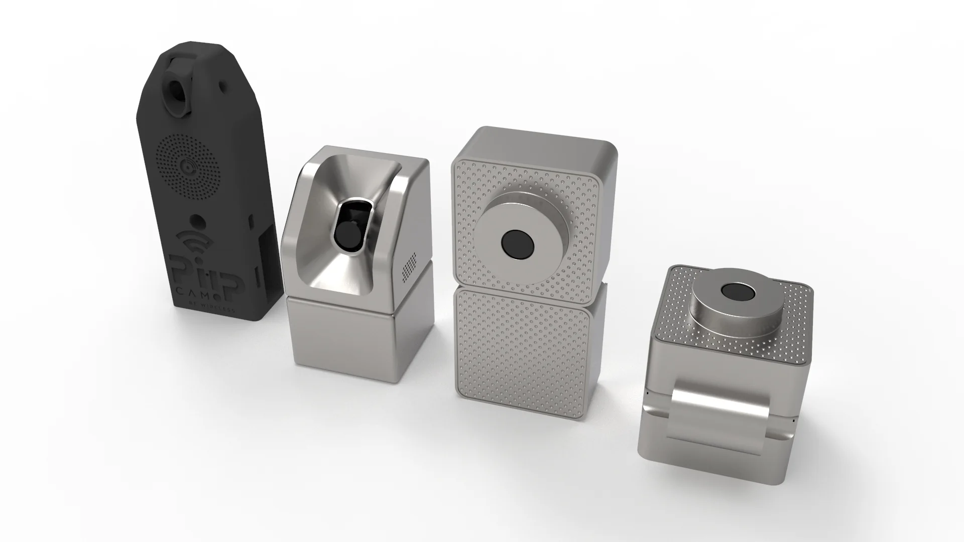
From enclosure concepts
to a manufacturable system.

The project evolved through multiple enclosure directions before converging on a compact modular architecture better aligned with usability, cooling, electronics integration and production requirements.

Early Piip Camo enclosure design explorations

Functional development

Designed to be
built and tested.

The redesign progressed beyond concept development into engineering, functional prototyping and pre-production, including enclosure refinement, battery-interface development and prototype coordination.

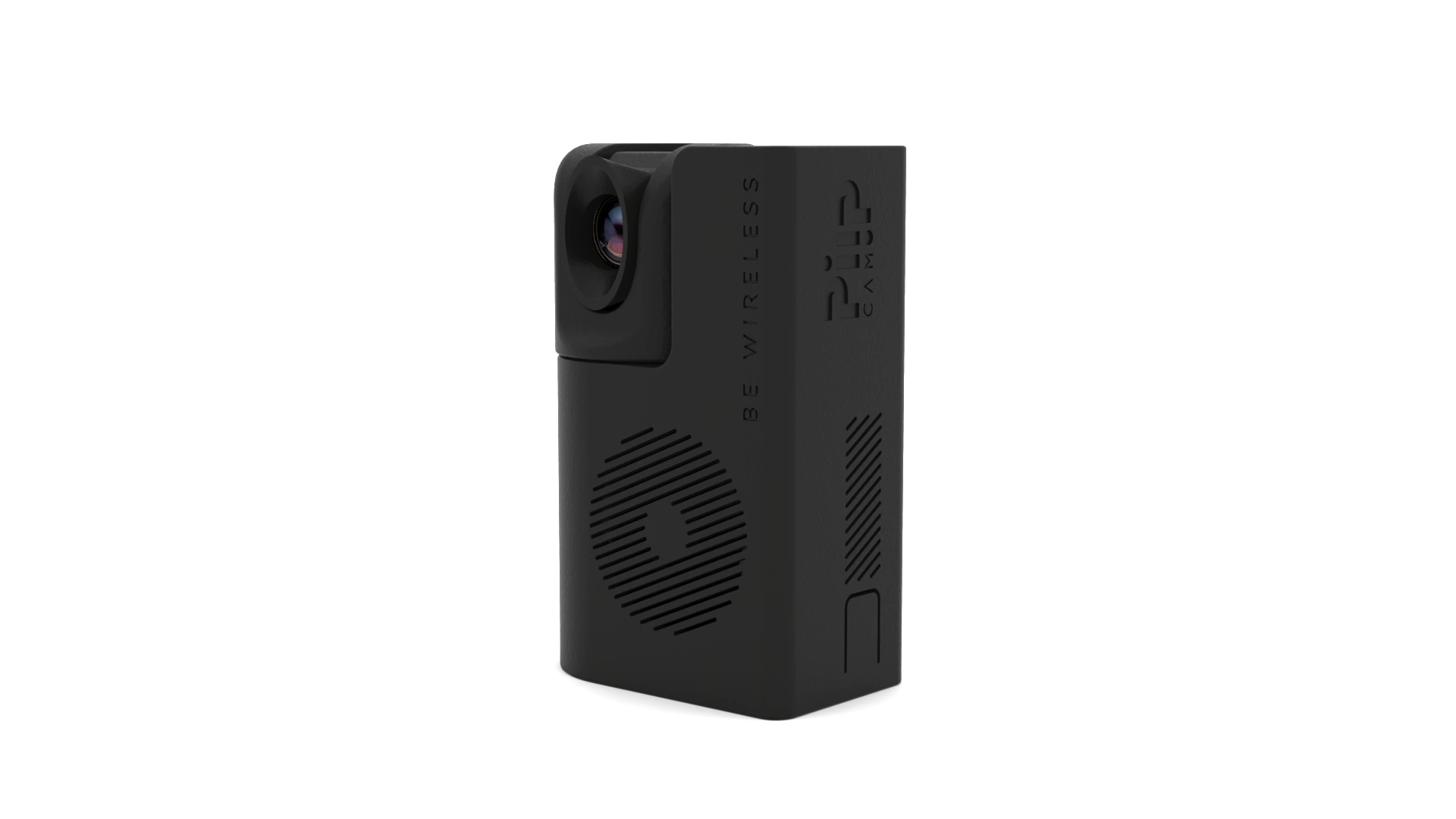
Final upper Piip Camo camera and electronics moduleFinal Piip Camo removable battery module

Streaming On Set × Innou

Portable hardware,
engineered around
the way it is used.

A redesign combining industrial design, electronics packaging, thermal management, modular power and practical on-set usability.
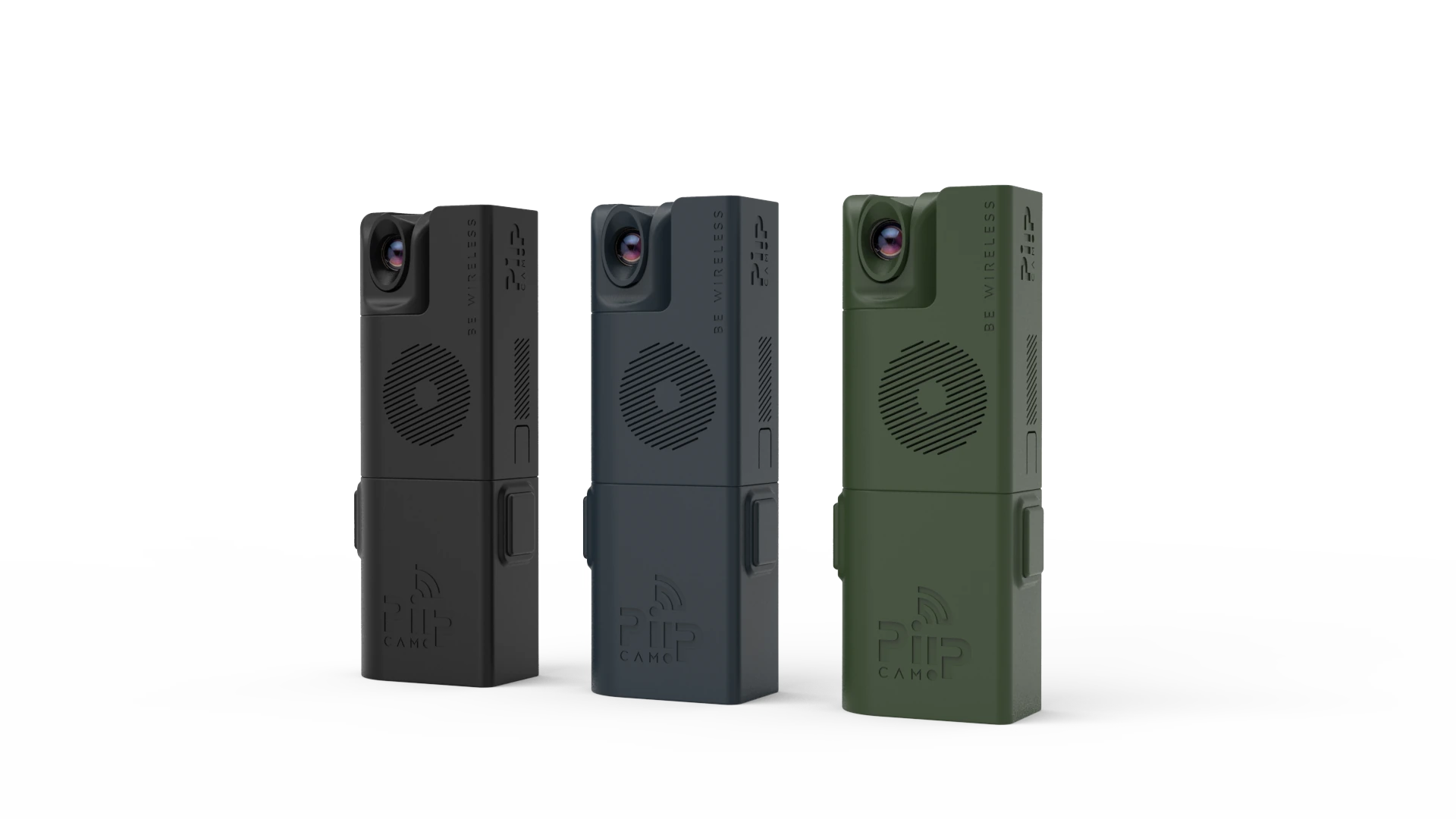
Final Piip Camo product variants

07 / Selected project

AER

A physical–digital platform for customizable contemporary hand fans.

Industrial Design · Digital Product · UX/UI · Generative AI · Production System

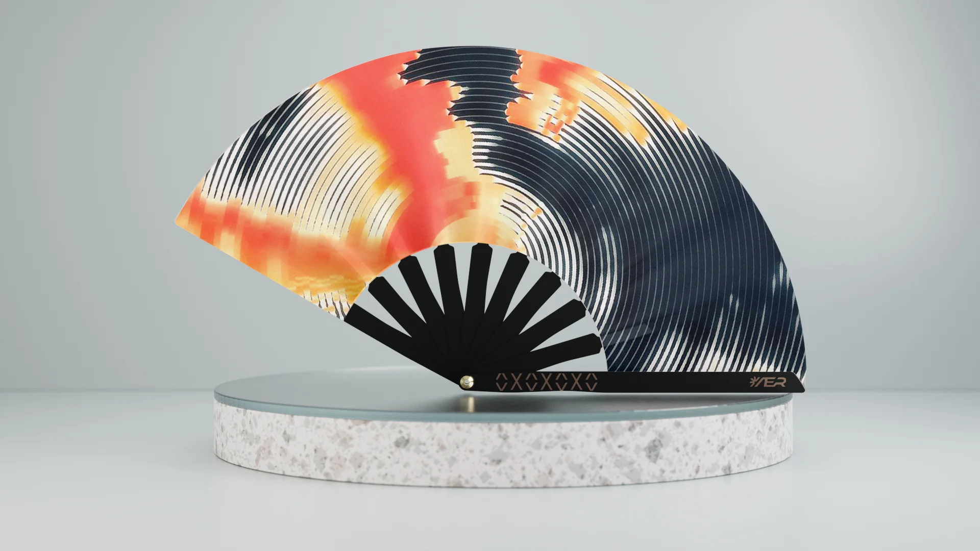
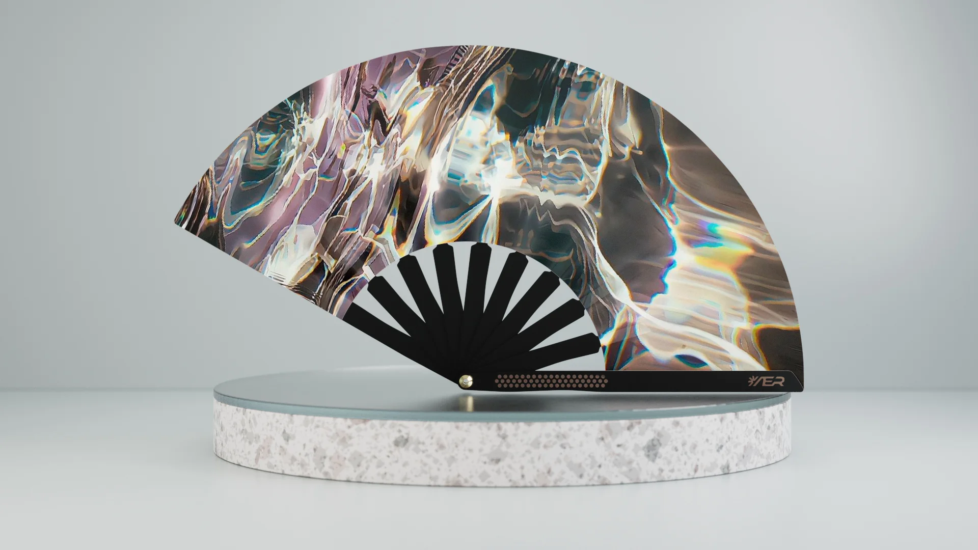
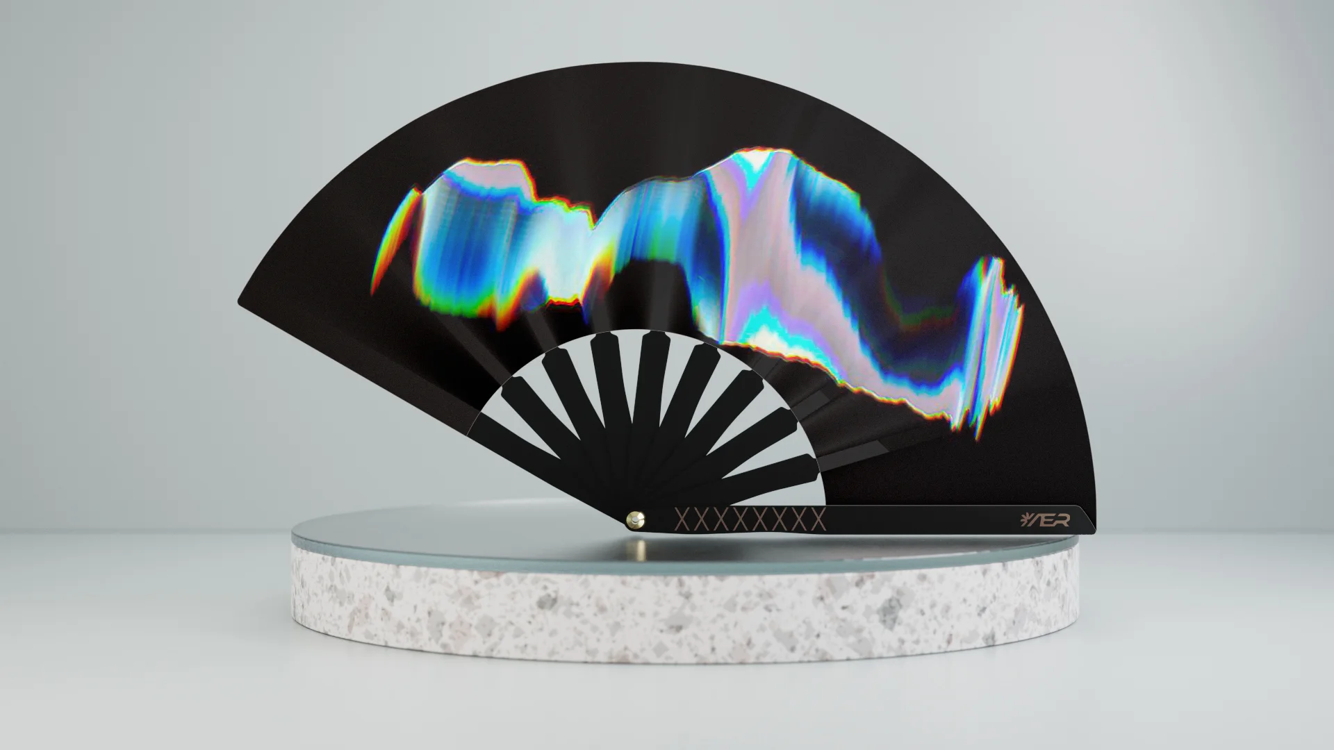
AER contemporary hand fan with a dark iridescent custom artwork

Physical product

A traditional object,
rebuilt as a system.

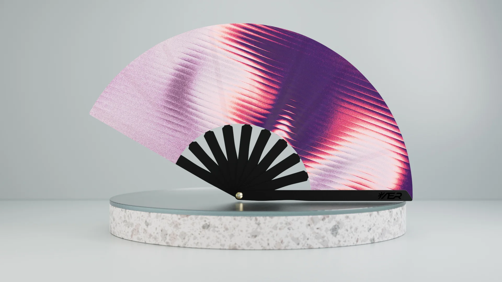
AER reinterprets the hand fan as a contemporary configurable product. Its architecture combines reusable structural components with interchangeable visual surfaces, allowing multiple collections and custom editions to be produced from the same core system.

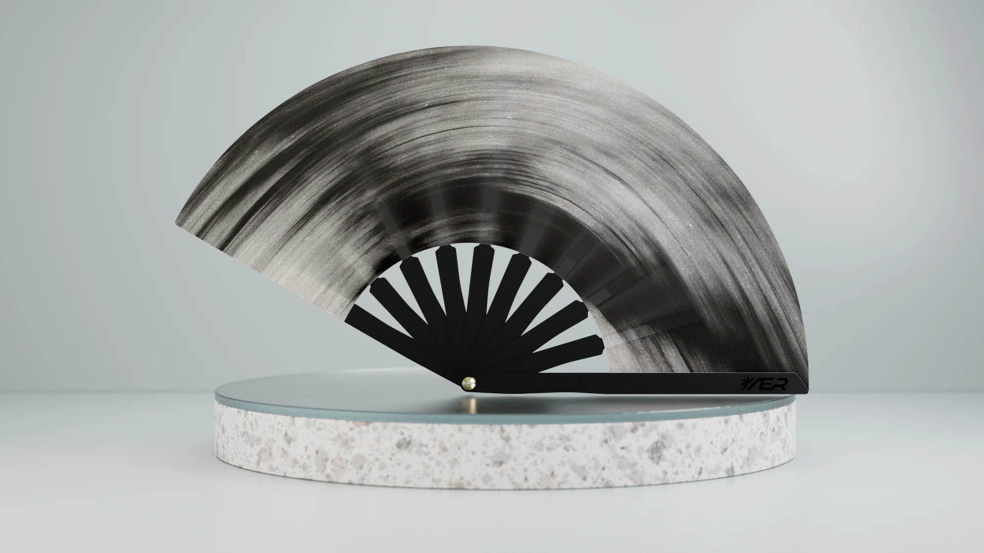
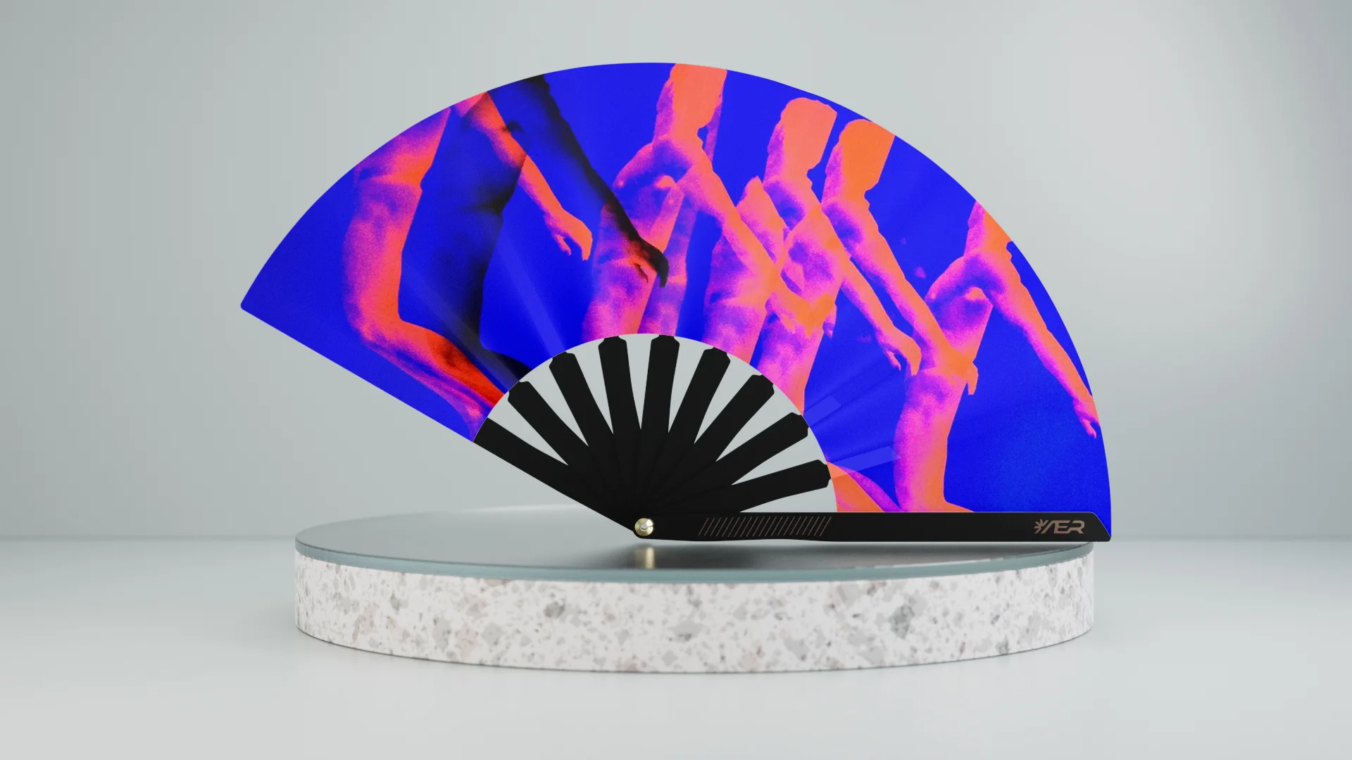
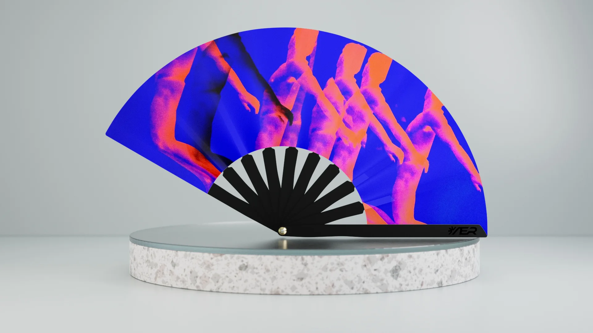
Full AER fan showing its shared black structure and interchangeable printed surface

Product ecosystem

The product does not end
at the object.

The physical fan was developed alongside the digital tools required to configure, generate, validate and manufacture each artwork. Product design, UX and production logic therefore had to be developed as one connected workflow.

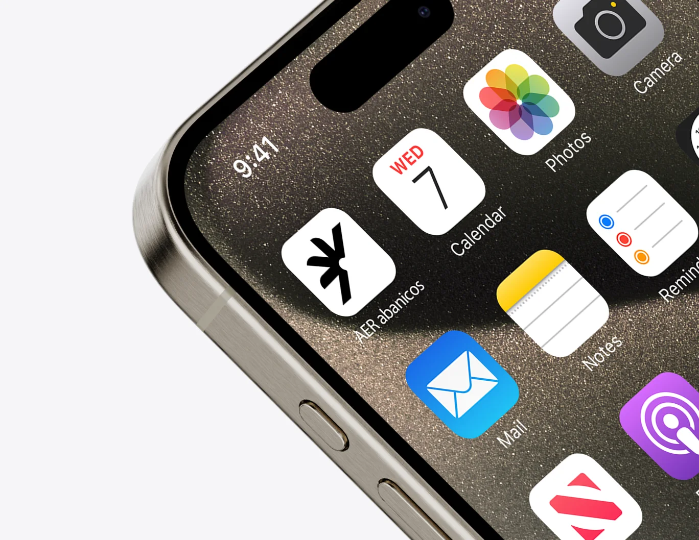
Monochrome AER hand fan representing the physical productAER digital-product icon shown on a mobile phone

Generative workflow

From an idea
to a manufacturable artwork.

A custom generation workflow allows visual concepts to be transformed into artwork compatible with the fan geometry and production constraints.

The system handles the transition between creative generation and technical output, including image composition, printable areas and production-ready files.

Design for manufacturing

Creative freedom,
inside production rules.

Artwork generation is constrained by the physical fan architecture, printing requirements and manufacturing tolerances. The digital experience therefore guides creative decisions while preserving a valid production output.

Finished AER fan demonstrating artwork fitted precisely to its physical geometry
  • Format
  • Print area
  • Colour
  • Geometry
  • Production file

UX/UI

A complex workflow
made understandable.

The interface connects artwork generation, configuration and production requirements through a guided user journey designed to hide unnecessary technical complexity.
Close view of the AER application touchpoint on an iPhone
Physical constraints translated into a guided digital experience

System development

Digital input.
Physical output.

Behind the interface, the project includes an automated workflow for artwork processing, technical validation and production documentation, reducing manual intervention between customization and manufacturing.

  1. 01Customise
  2. 02Generate
  3. 03Validate
  4. 04Prepare
  5. 05Manufacture

Product experience

One product experience,
from screen to packaging.

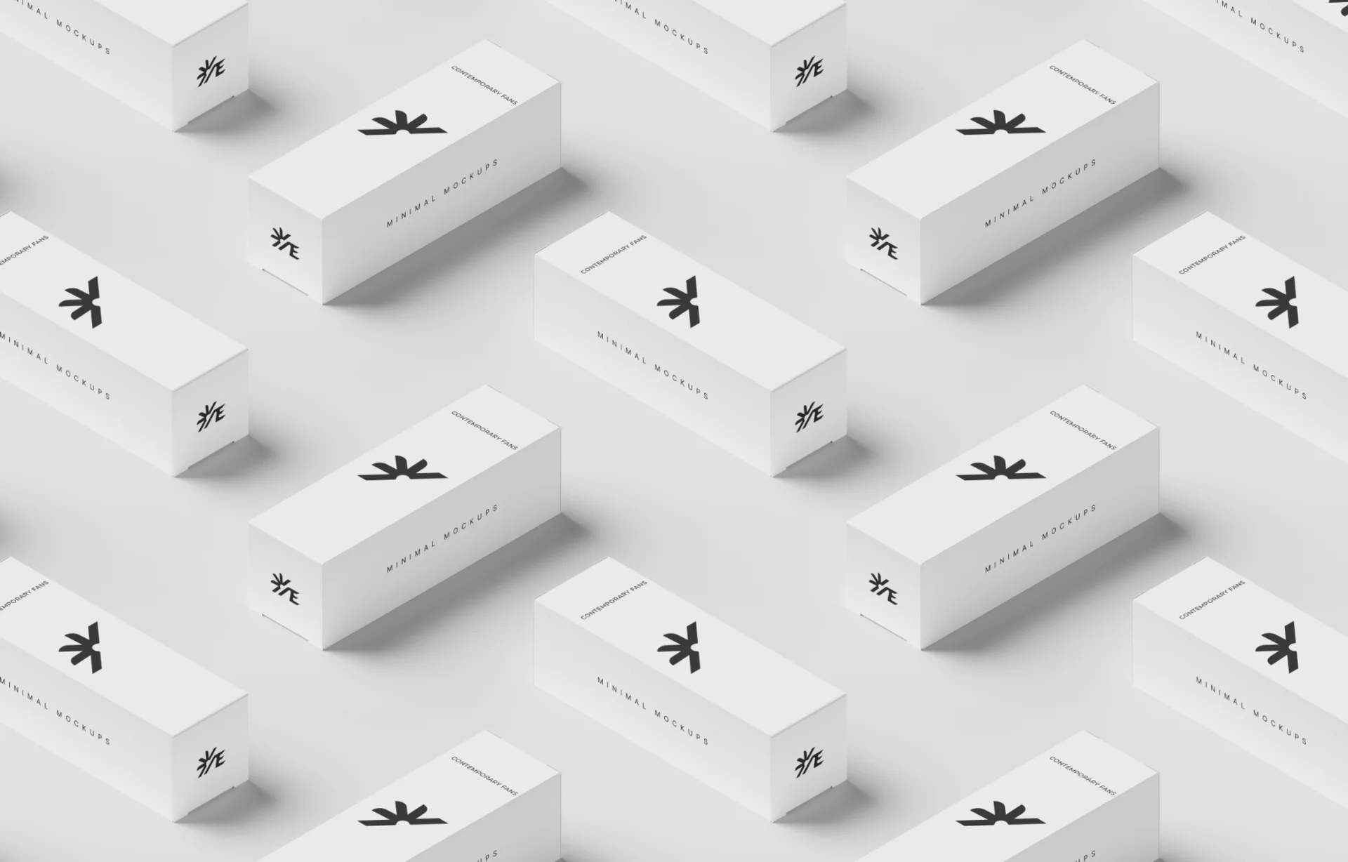
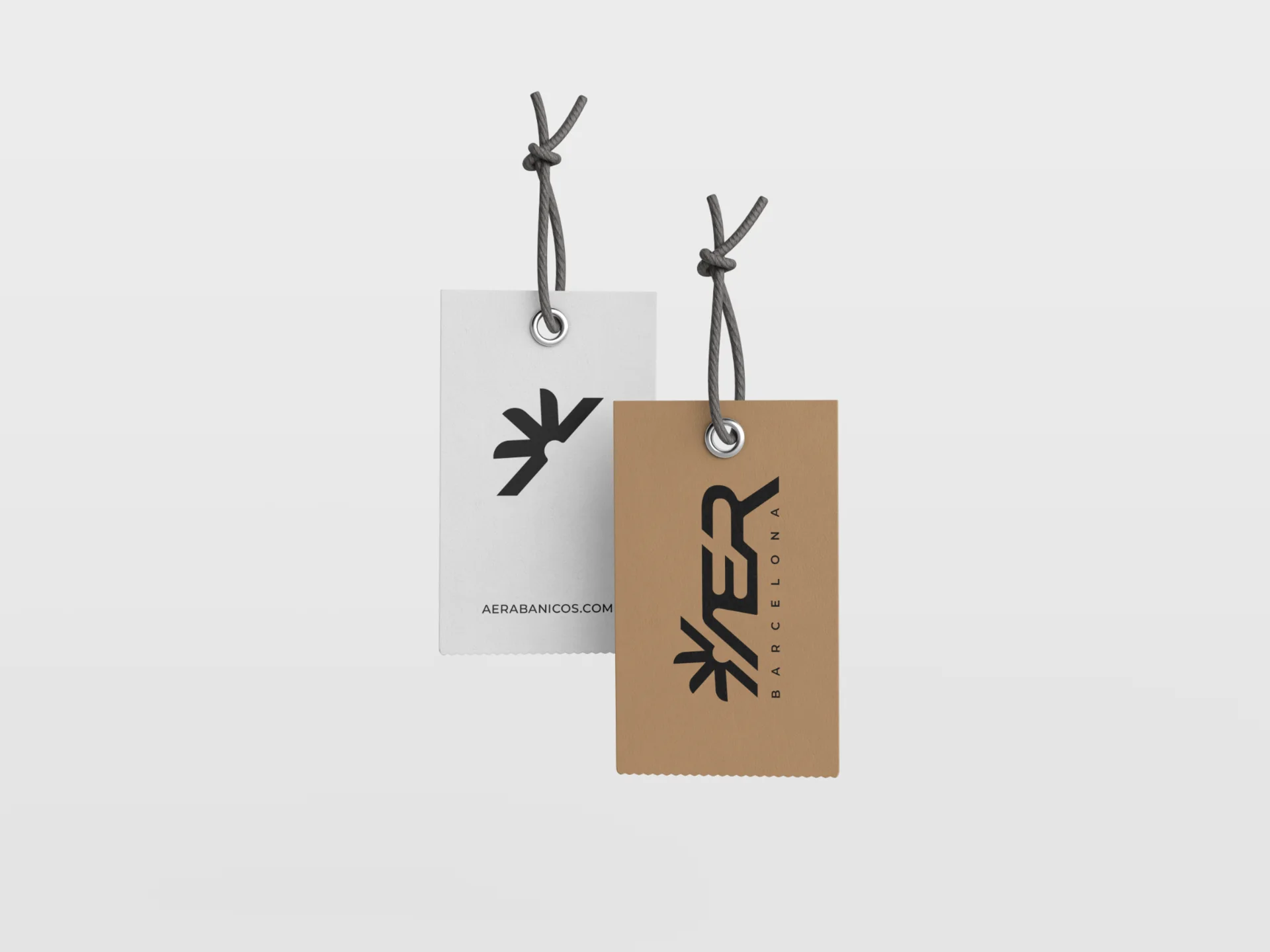
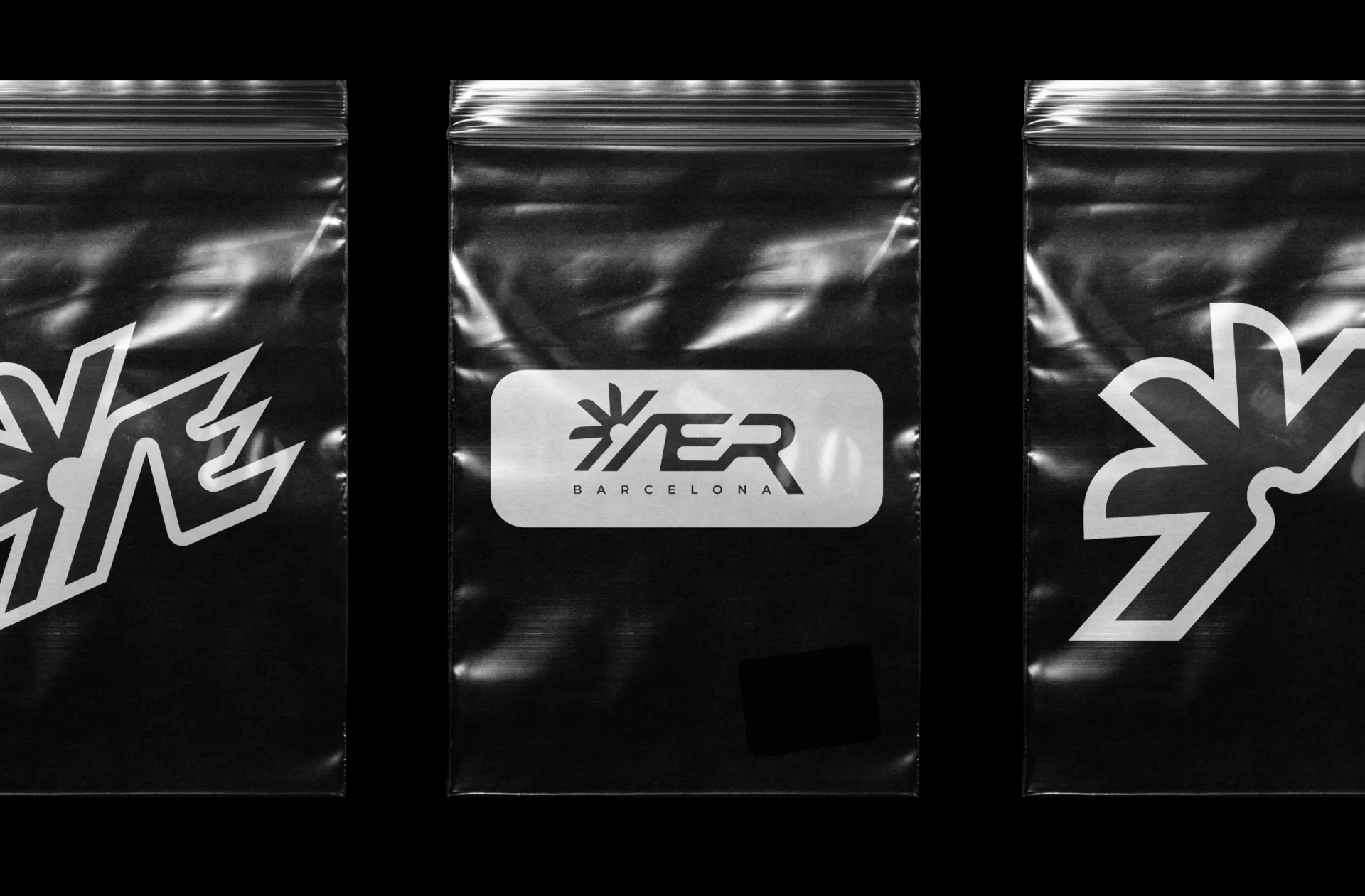
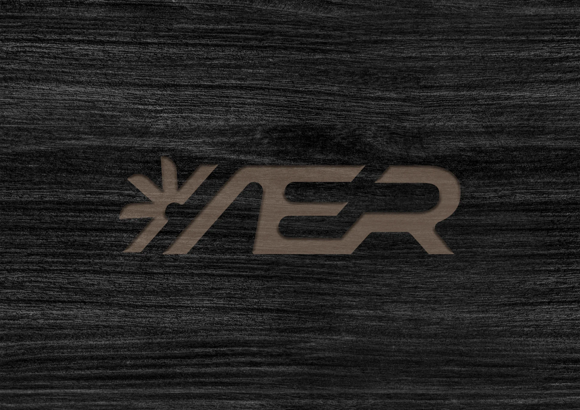
The same system extends into packaging, labels, product identification and other physical brand touchpoints, creating continuity between the digital configuration experience and the delivered object.

AER product boxes arranged as a packaging systemAER product-identification hang tagsBlack protective AER fan bags with product labelsAER logo detail engraved into a dark material surface

Outcome

A physical product
built around a digital system.

AER brings industrial design, customization, generative tools and manufacturing into a single product ecosystem — allowing a traditionally static object to become configurable, scalable and digitally connected.

Final AER physical fan with a custom iridescent artwork

08 / Selected project

UX/UI & Web Work

[TEXT PENDING]
Interface overview[IMAGE PENDING]
Large UI crop[IMAGE PENDING]
Flow[IMAGE PENDING]
Interaction[IMAGE PENDING]

[TEXT PENDING]

12 / Contact sheet

Additional
selected projects

  • [IMAGE PENDING]

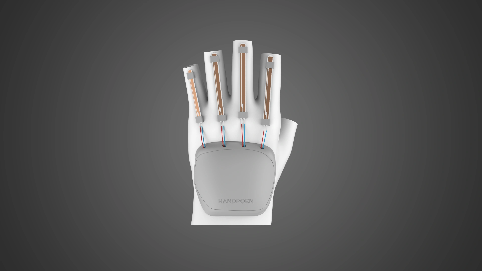
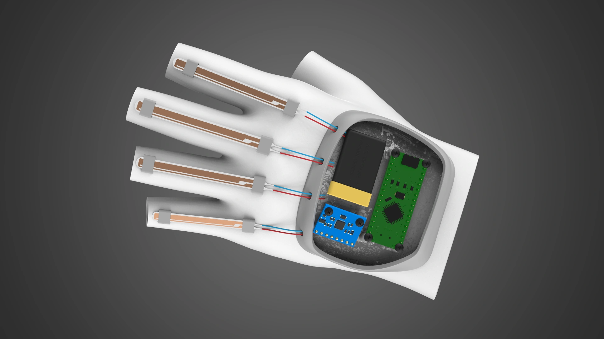
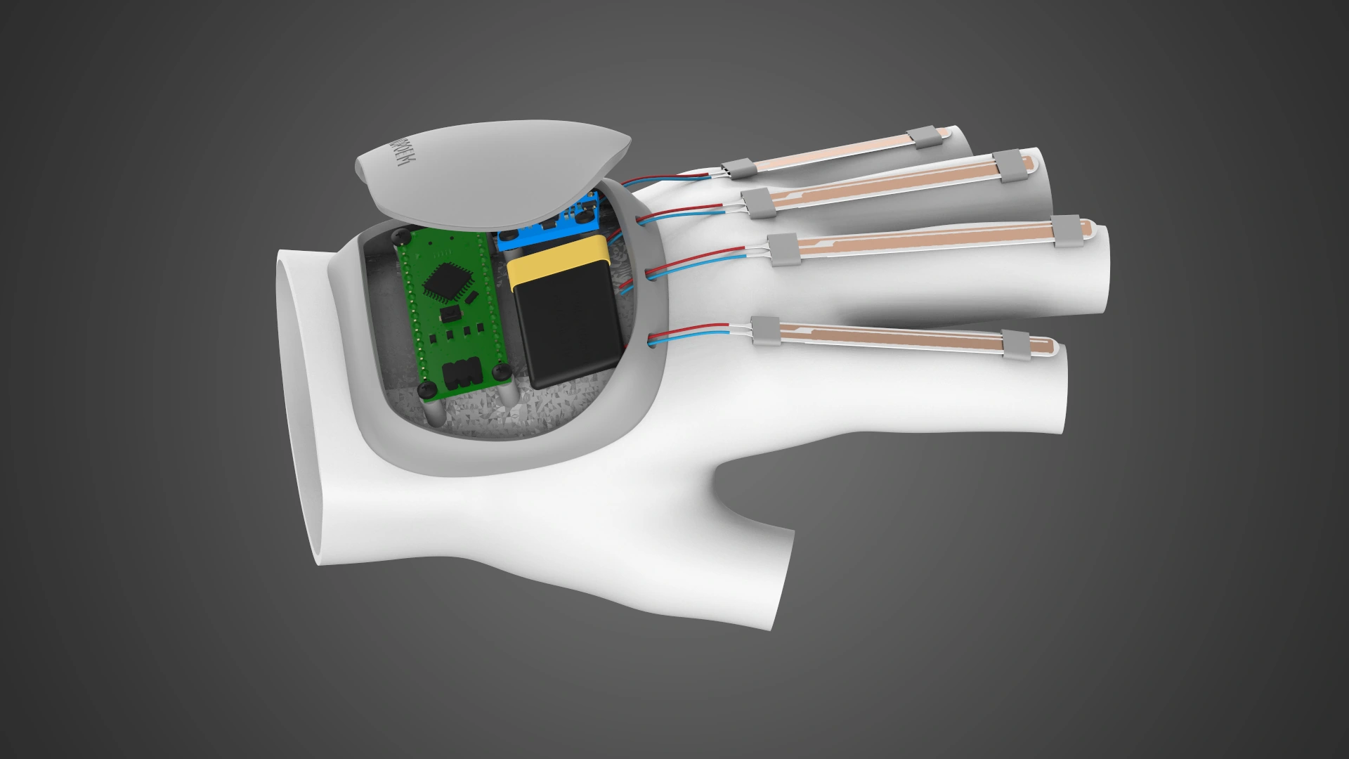
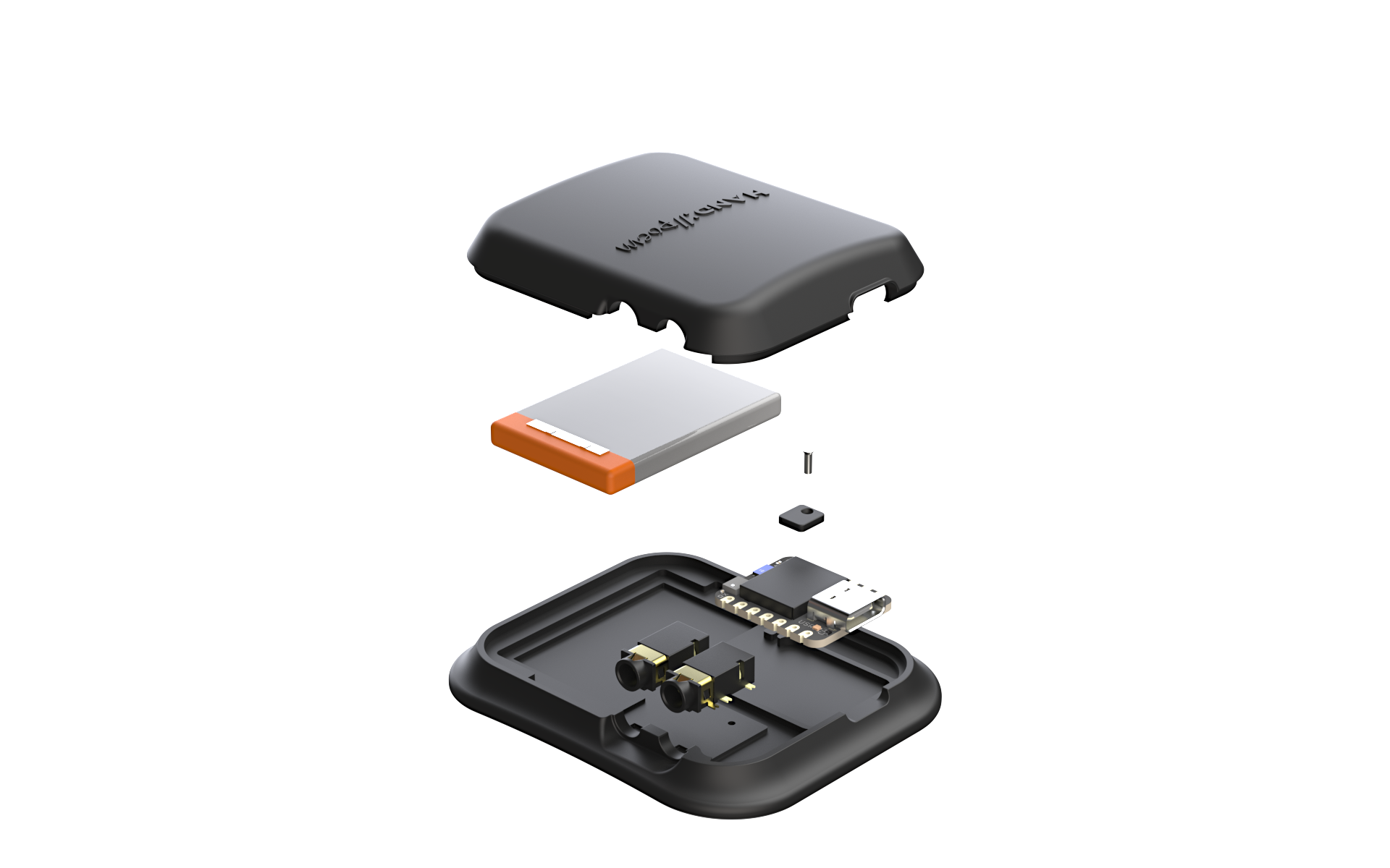
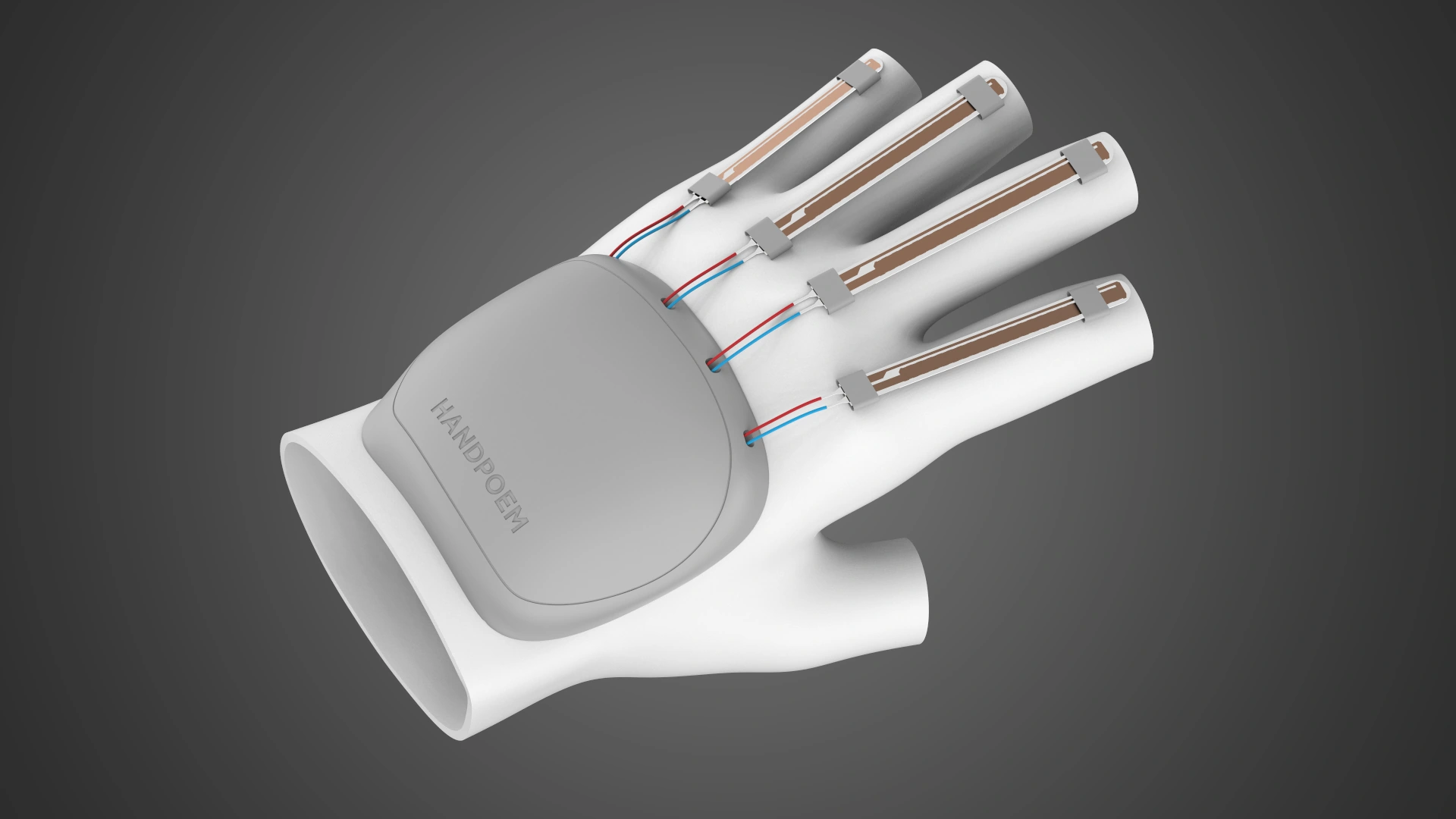
    Handpoem

    [TEXT PENDING]

  • [IMAGE PENDING]

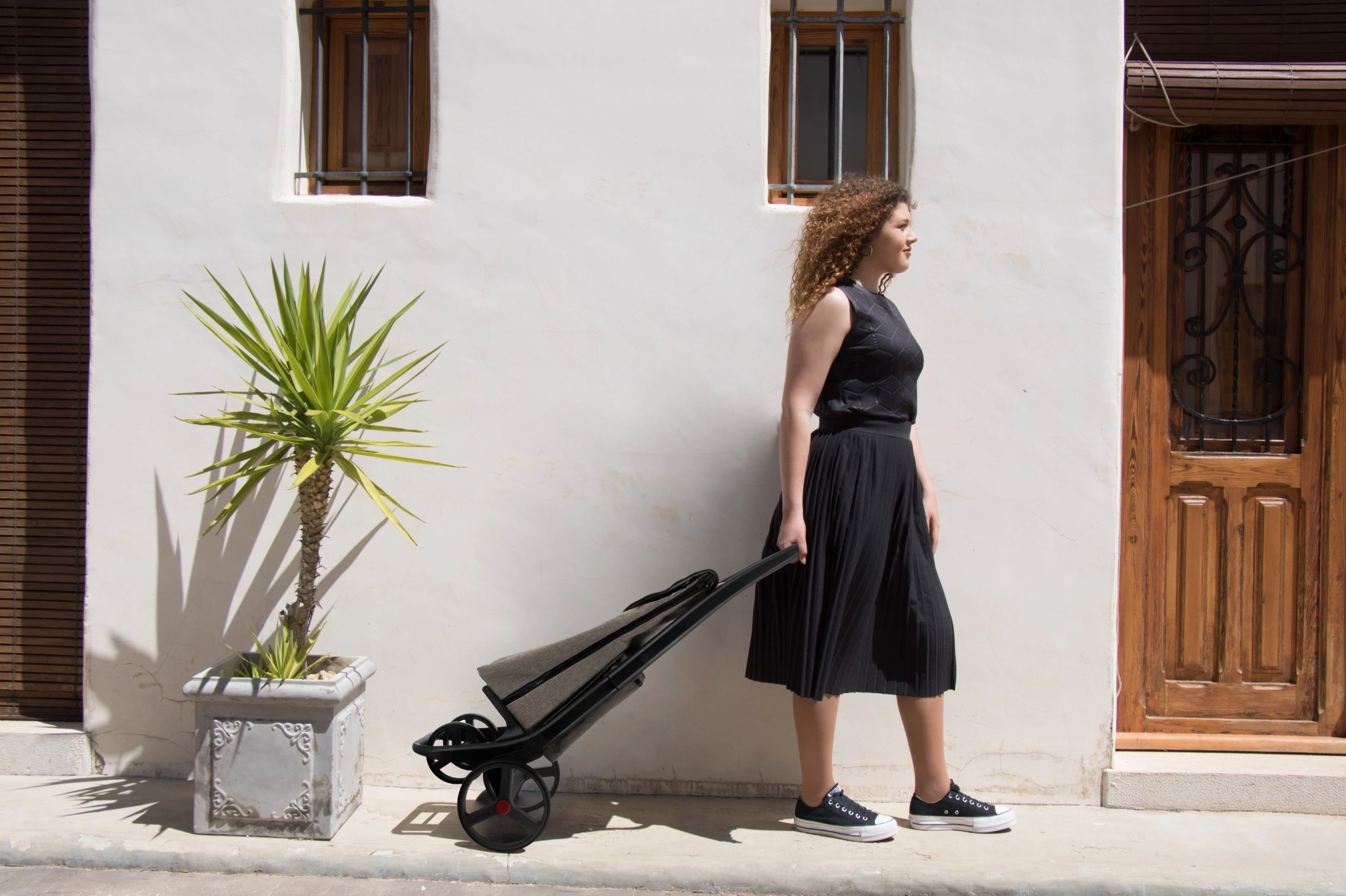
    Rolser

    [TEXT PENDING]

  • [IMAGE PENDING]

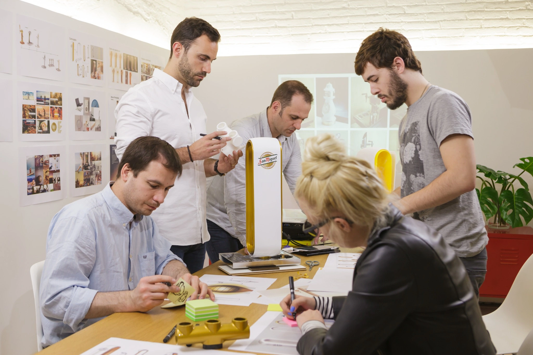
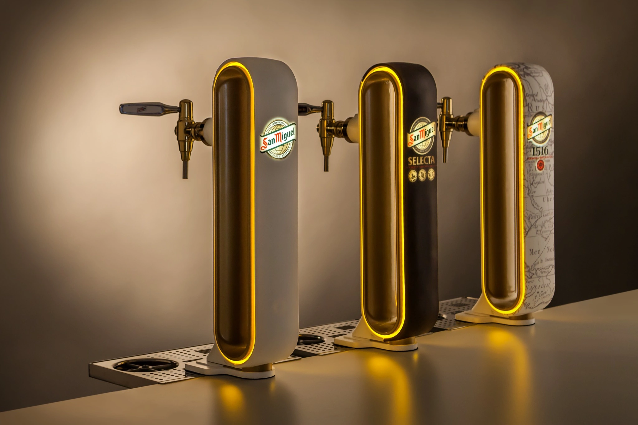
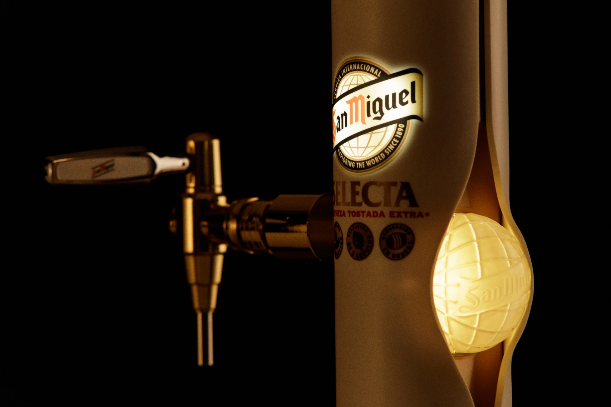
    San Miguel

    [TEXT PENDING]

  • [IMAGE PENDING]

    Carbi

    [TEXT PENDING]

13 / End frame

Diego A.
López Ratti

  • Master's in Biomedical Engineering — ongoing
  • Master's in Sustainable Product Design & Ecodesign
  • Bachelor's Degree in Product Design
  • Previous studies in Medicine

Contact

[EMAIL PENDING]

[LINKEDIN PENDING]